
Display apparatus with a time domain multiplex driving circuit

a technology of multiplex driving circuit and display apparatus, which is applied in the direction of static indicating devices, non-linear optics, instruments, etc., can solve the problems of reducing the aperture ratio of the display panel, and reducing the number of scanning times. , the effect of reducing the number of data lines for driving

Inactive Publication Date: 2006-02-14
INNOLUX CORP
View PDF2 Cites 12 Cited by
  • Summary
  • Abstract
  • Description
  • Claims
  • Application Information

AI Technical Summary

Benefits of technology

[0016]It is therefore an objective of the invention to provide a display apparatus with a new time domain multiplex driving circuit for driving the pixels of the display apparatus in order to achieve a reduced number of data lines for driving the display apparatus. Meanwhile, a reduced scanning time can be achieved, and the luminance uniformity as well as the display quality can be maintained.

Problems solved by technology

First, a large number of data lines are needed.
Connecting all data lines to the corresponding outer leads of the tape carrier packages thus becomes difficult.
Thirdly, the aperture ratio of the display panel will be decreased since the number of the data lines is so large.
However, the conventional time domain multiplex driving circuit described above has the following disadvantage.
First, a longer scanning time for pixels is needed.
Secondly, the luminance uniformity of the display cannot be achieved due to feed-through effect.
In addition, the luminance of a display panel whose pixels are arranged according to the structure shown in FIG. 3 would be non-uniform when identical data signals are applied to all pixels of the display.
For the display panel according to FIG. 3, each pixel of the odd (or even) pixel columns includes two TFTs and each pixel of the even (or odd) pixel columns includes one TFT, so that the equivalent capacitances of the adjacent pixel columns are different, thus resulting in the non-uniformity of luminance.
The display quality of the liquid crystal display may be degraded because of the odd-even line effect.
First, the scanning time needed to activate pixels is longer.
Secondly, the luminance of the display is not uniformly over the whole panel.
Thirdly, the odd-even line effect degrades the display quality.

Method used


Image

  • Display apparatus with a time domain multiplex driving circuit
  • Display apparatus with a time domain multiplex driving circuit
  • Display apparatus with a time domain multiplex driving circuit

Examples


Embodiment Construction

[0027]The feature of the invention is to provide a new switching device structure of the time domain multiplex driving circuit. According to the invention, the disadvantages of the conventional time domain multiplex driving circuit can be improved.

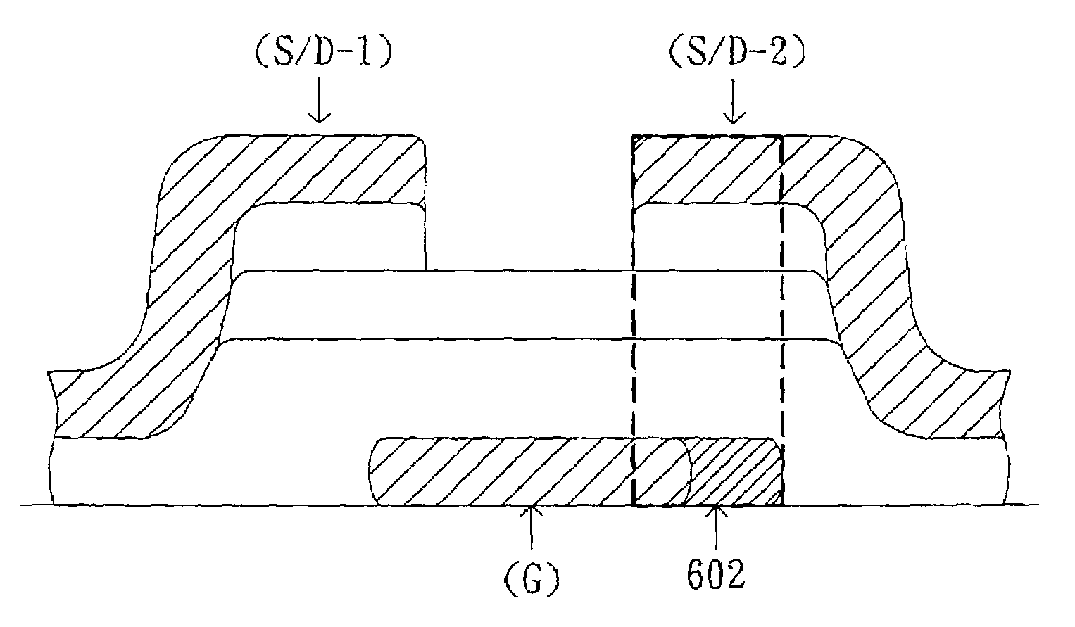
[0028]Referring to FIG. 5, a time domain multiplex driving circuit is shown according to a first embodiment of the invention. Take the pixel LP(m,n) and RP(m,n) shown in FIG. 5 for example; both pixels are coupled to the scan line Sm and the data line Dn. The pixel LP(m,n) is set on the left side of the data line Dn, and the pixel RP(m,n) is set on the right side of the data line Dn, as shown in FIG. 5. The switching device of the pixel RP(m,n) includes two switches M21 and M22 which are used for selectively transmitting the data signal loaded on the data line Dn to the pixel RP(m,n). The switching device of the pixel LP(m,n) includes a switch M1 which is used for selectively transmitting the data signal on the data line Dn to the pixel LP...


PUM

PropertyMeasurementUnit
capacitancesaaaaaaaaaa
capacitanceaaaaaaaaaa

Abstract

A display apparatus with a time domain multiplex driving circuit includes a first scan line, a first data line perpendicular to the first scan line, a first pixel and a second pixel which are set on different sides of the first data line and coupled to the same data line, a first switching device and a second switching device set in the first and second pixel respectively. The first switching device is for selectively transmitting a pixel signal from the data line to the first pixel and the second switching device is for selectively transmitting a pixel signal from the data line to the second pixel. When the pixel signals of equal magnitude are individually applied to the first and second pixels, the feed-through voltages of the first and second pixels are substantially equal.

Description

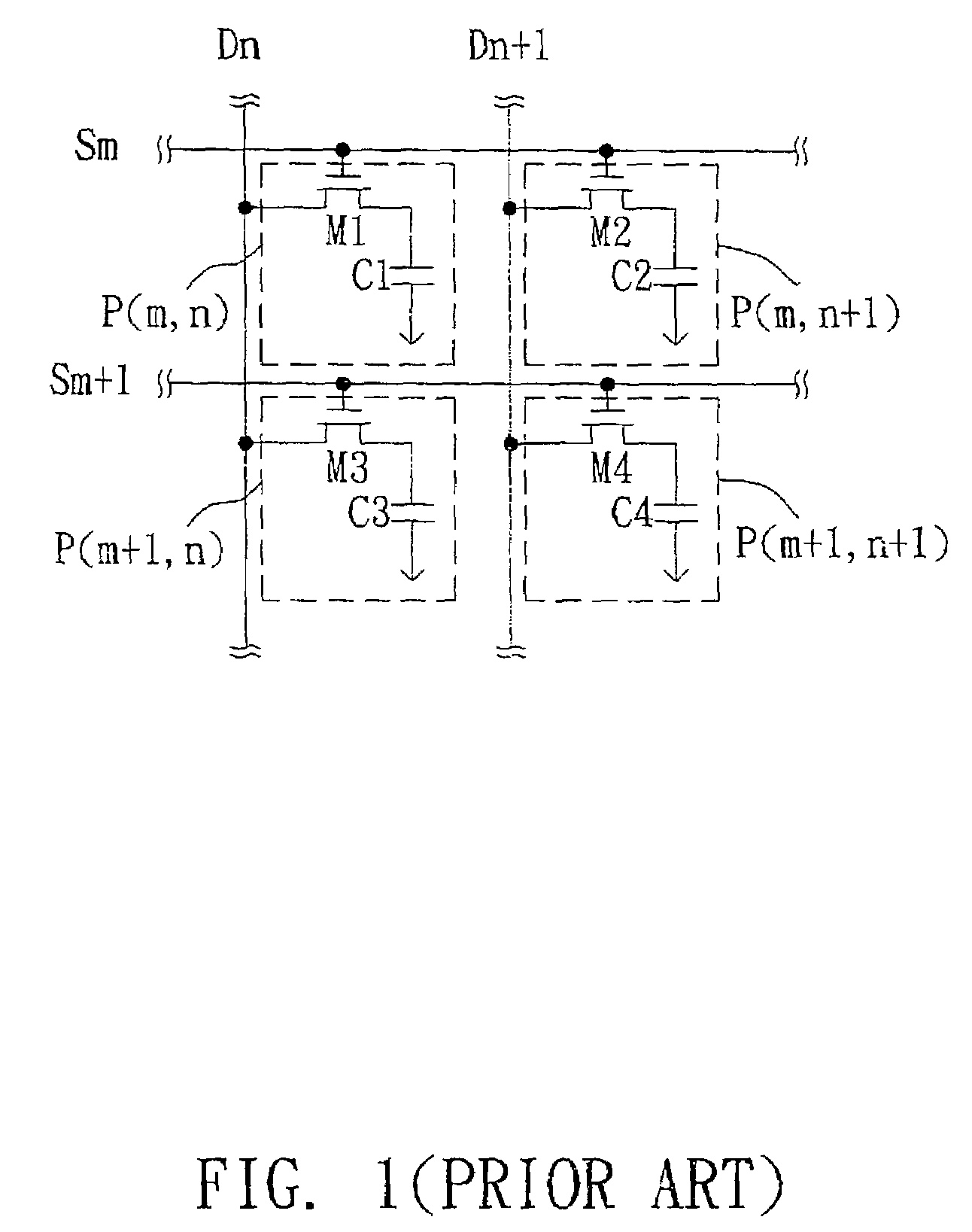
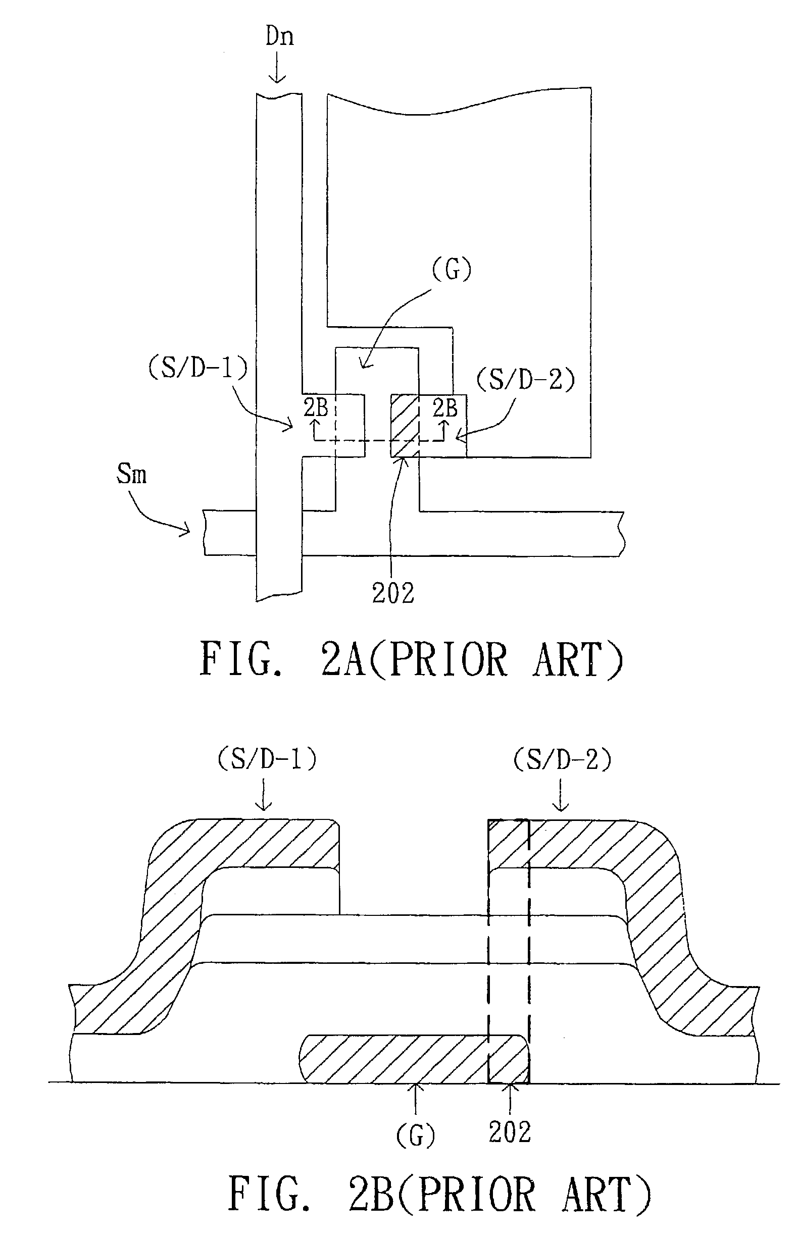
[0001]This application claims the benefit of Taiwan application Ser. No. 091104167, filed on Mar. 6, 2002.BACKGROUND OF THE INVENTION[0002]1. Field of the Invention[0003]The invention relates in general to a display apparatus, and more particularly to a display apparatus with a time domain multiplex driving circuit.[0004]2. Description of the Related Art[0005]Featuring the favorable properties of thinness, lightness and generating low radiation, liquid crystal display (LCDs) have been widely used in computer systems. A LCD panel typically uses an active matrix circuit for driving its pixels. In order to achieve a higher resolution and aperture ratio of the panel products, the industry focuses on developing improved driving circuits and associated driving methods, as well as reducing both manufacturing costs and size of the driving circuit apparatus.[0006]FIG. 1 shows a circuit diagram illustrating a conventional LCD panel. The display panel includes a plurality of pixels (P) which a...

Claims


Application Information

Patent Timeline
Patent Type & Authority Patents(United States)
IPC IPC(8): G09G3/36G02F1/1368G09G3/00G02F1/133G09G3/20
CPCG09G3/3659G09G2320/0233G09G2300/0814G09G3/3677
Inventor LEE, HSIN-TALIN, WEN-CHIEH
Owner INNOLUX CORP
Learn More