Magnetic disk drive with structure for avoiding DC magnetic disturbance on a disk surface

Active Publication Date: 2006-02-14
KK TOSHIBA
View PDF14 Cites 71 Cited by
  • Summary
  • Abstract
  • Description
  • Claims
  • Application Information

AI Technical Summary

Benefits of technology

[0016]An object of the present invention is to provide a disk drive of the perpendicular magnetic recording t

Problems solved by technology

In other words, the read head 30 may output a read signal whose quality is deteriorated, in which case a read error will

Method used


Image

  • Magnetic disk drive with structure for avoiding DC magnetic disturbance on a disk surface
  • Magnetic disk drive with structure for avoiding DC magnetic disturbance on a disk surface
  • Magnetic disk drive with structure for avoiding DC magnetic disturbance on a disk surface

Examples


first modification

[0051](First Modification)

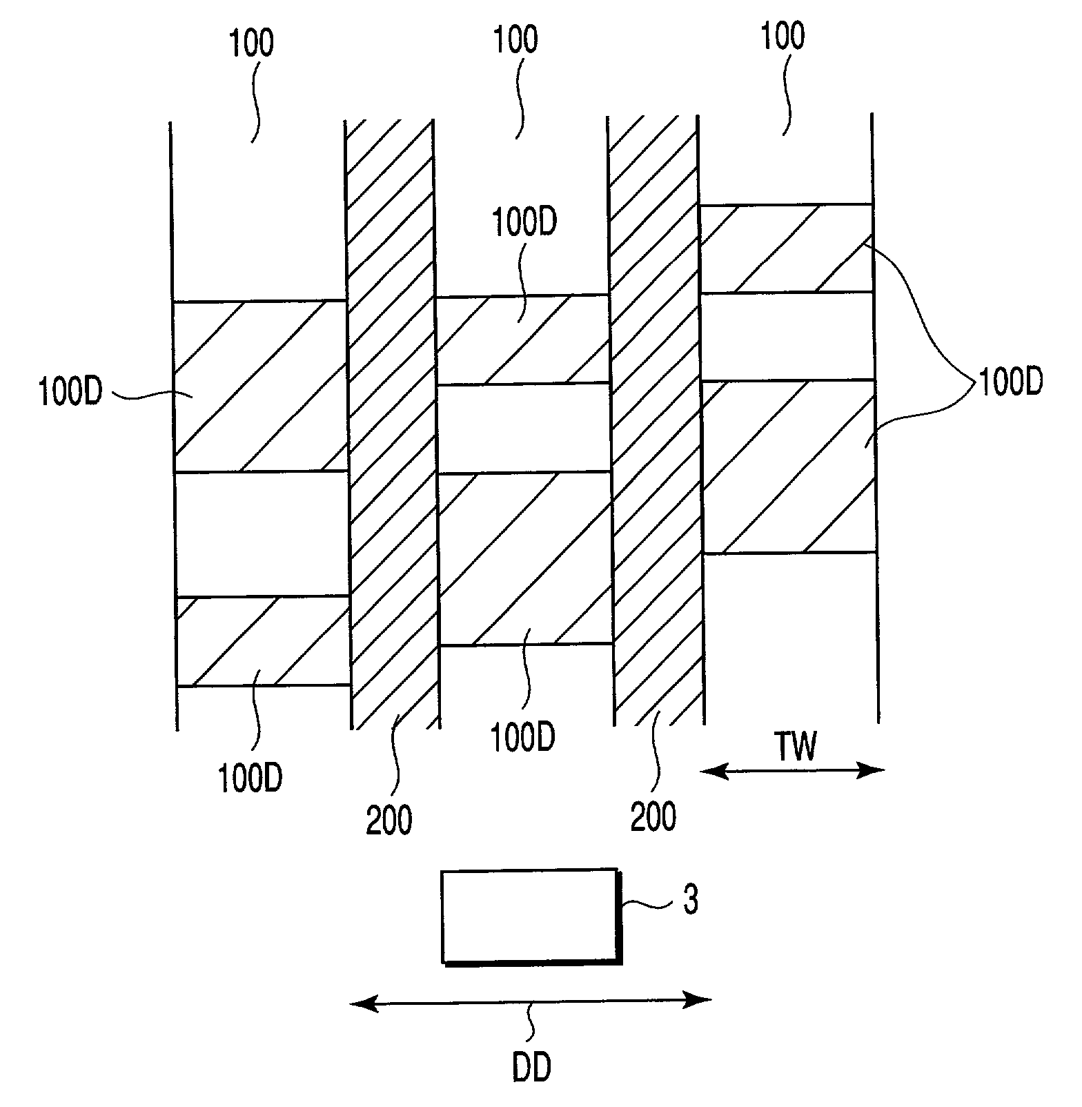
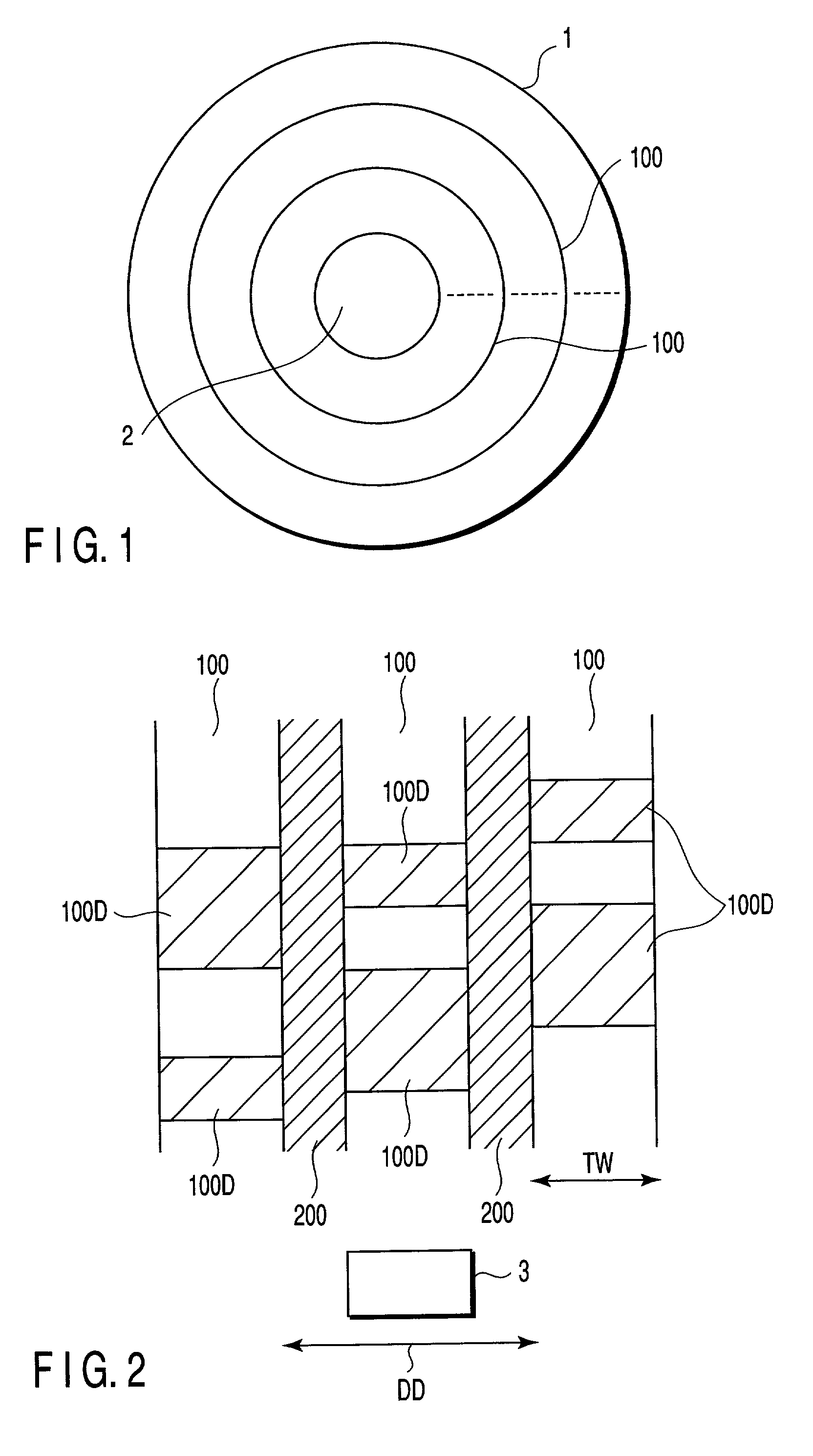
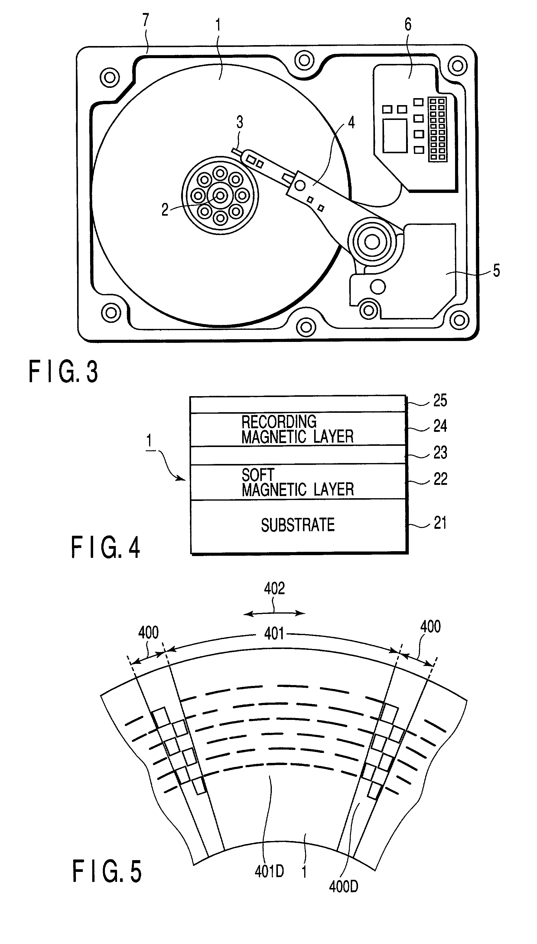
[0052]FIG. 8 shows a first modification of the above embodiment. In the above embodiment, the AC magnetized region is formed only in the data area401. In contrast, according to this modification, an AC magnetized region 700 is formed also in the servo area 400, as well as in the data area. The AC magnetized region 700 is formed in the same manner as in the case of the above embodiment: a high-frequency magnetic pattern equal to or higher than the maximum recording frequency in the drive is recorded by perpendicular magnetic recording, thereby forming the AC magnetized region 700. The AC magnetized region 700 is a non-signal region where no servo data (servo signal) is recorded (a boundary region between signal regions). In the conventional disk, the servo area is a uniformly DC magnetized (DC erase) region.

[0053]With the above structure, when the magnetic head 3 travels within the servo area 400 and reads servo data by means of the read head, the possibilit...

second modification

[0054](Second Modification)

[0055]FIG. 9 shows a second modification of the above embodiment. In this modification, instead of AC magnetizing the GB area as in the above embodiment, residual magnetization (remanence) of the GB area is substantially zeroed. With this structure, when the magnetic head 3 is located above the target track 100 as shown in FIG. 8, influence of magnetic disturbance on the read head, due to leakage magnetic field from the GB area 200, can be effectively suppressed.

[0056]In general, it is confirmed that, when the magnetic disk 1 receives an attenuating alternate magnetic field or heated to a certain degree, the magnetization turns to a random state and the remanence on the disk surface is substantially zero. Thus, in this modification, the overall surface of the disk 1 is subjected to an AC demagnetizing process or heat demagnetizing process prior to the track formatting. As a result, the overall surface of the disk is kept in a random magnetized state (in wh...


PUM


Abstract

A disk drive of a perpendicular magnetic recording type uses a double-layered disk. The disk has a plurality of tracks for storing data and a non-recording region (GB area) between tracks. Not a DC magnetized pattern but an AC magnetized pattern or a random magnetized pattern is recorded in the GB area. With this structure, it is possible to prevent an influence of magnetic disturbance due to a DC magnetic field on the surface of the disk.

Description

CROSS-REFERENCE TO RELATED APPLICATIONS[0001]This application is based upon and claims the benefit of priority from the prior Japanese Patent Application No. 2001-023972, filed Jan. 31, 2001, the entire contents of which are incorporated herein by reference.BACKGROUND OF THE INVENTION[0002]1. Field of the Invention[0003]The present invention relates generally to a disk drive of perpendicular magnetic recording type, and more particularly to a magnetic disk drive with a structure for avoiding magnetic disturbance due to a DC magnetic field.[0004]2. Description of the Related Art[0005]In recent years, in the field of magnetic disk drives such as hard disk drives, a perpendicular magnetic recording method has been attracted public attention as technology of exceeding the limits of recording densities in a longitudinal magnetic recording method. As a disk drive that employs the perpendicular magnetic recording method, a disk drive using a double-layered disk recording medium (hereinafte...

Claims


Application Information

Patent Timeline
IPC IPC(8): G11B5/09G11B5/66G11B5/65G11B5/00G11B5/012G11B5/03G11B5/667G11B5/84
CPCG11B5/012G11B2005/0029G11B2005/0016G11B5/03
Inventor TAKEO, AKIHIKO
Owner KK TOSHIBA
Why Eureka
Try Eureka