Cleaning tape with surface protrusions formed by particles of predetermined size/density and non-magnetic metal evaporated film of predetermined thickness

Inactive Publication Date: 2006-02-14
SONY CORP
View PDF5 Cites 2 Cited by
  • Summary
  • Abstract
  • Description
  • Claims
  • Application Information

AI Technical Summary

Benefits of technology

[0026]Thus, it is possible to perform cleaning of magnetoresistive heads while preventing electrostatic discharge damage to magnetoresistive heads such as MR heads, GMR heads, and the like. Also, according to an embodiment of the cleaning head of the present invention, it is possible to suppress the wear on magnetoresistive heads

Problems solved by technology

However, the cleaning tape disclosed in the above mentioned Japanese unexamined patent publication no.
1996-315327 is optimized for high definition digital VTR systems, and is not suitable for magnetoresistive heads.
As a result, they are more likely to cause electrostatic discharge damage to magnetoresistive heads.
1996-315327 is used for cleaning magnetoresistive heads, because it is highly abrasive, it leads to excessive head wear.
When particles with a particle diameter of 60 nm˜100 nm are used, the amount of wear

Method used


Image

  • Cleaning tape with surface protrusions formed by particles of predetermined size/density and non-magnetic metal evaporated film of predetermined thickness
  • Cleaning tape with surface protrusions formed by particles of predetermined size/density and non-magnetic metal evaporated film of predetermined thickness
  • Cleaning tape with surface protrusions formed by particles of predetermined size/density and non-magnetic metal evaporated film of predetermined thickness

Examples


example 1

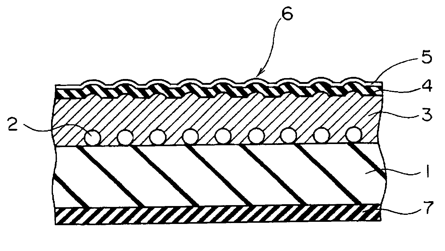
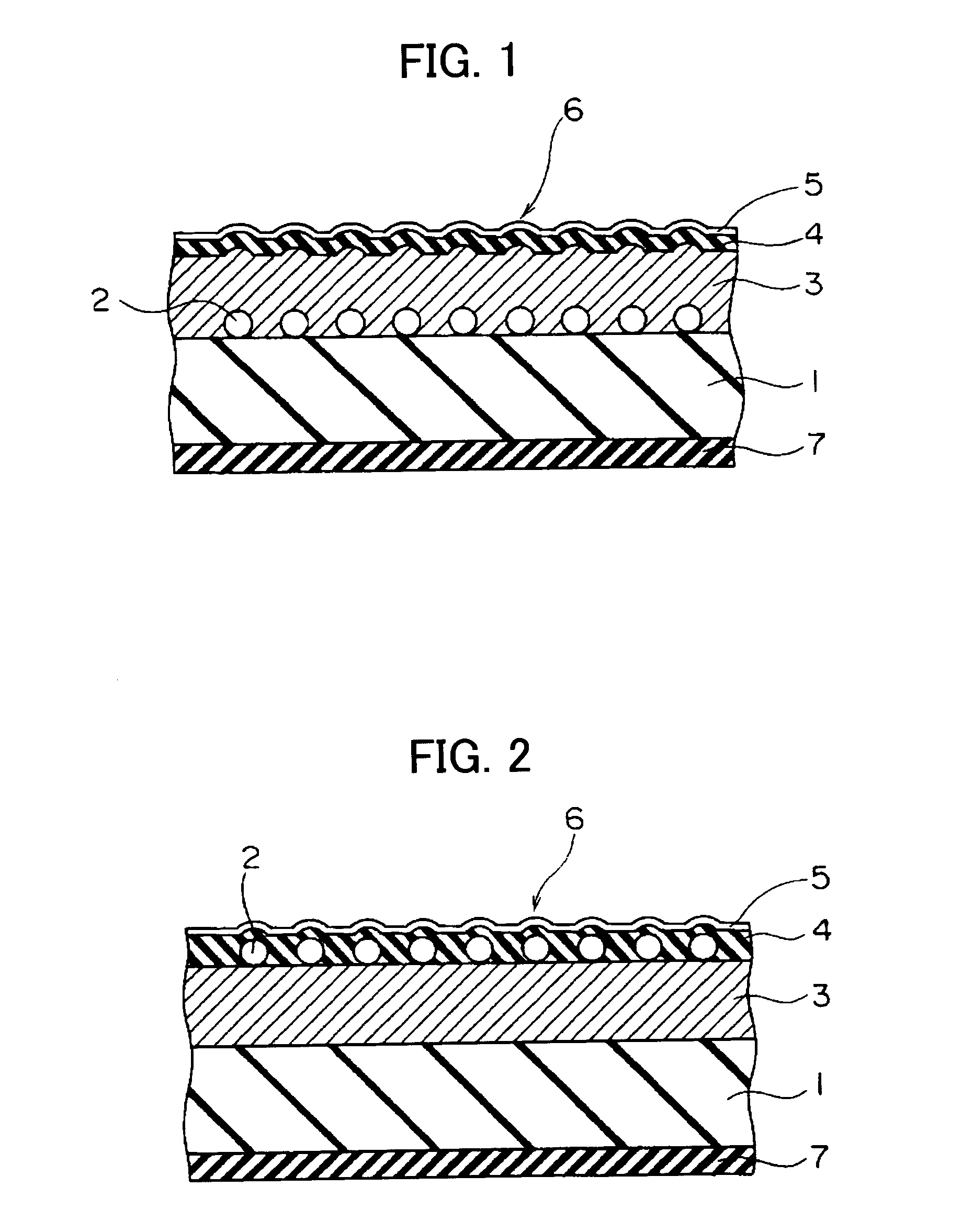
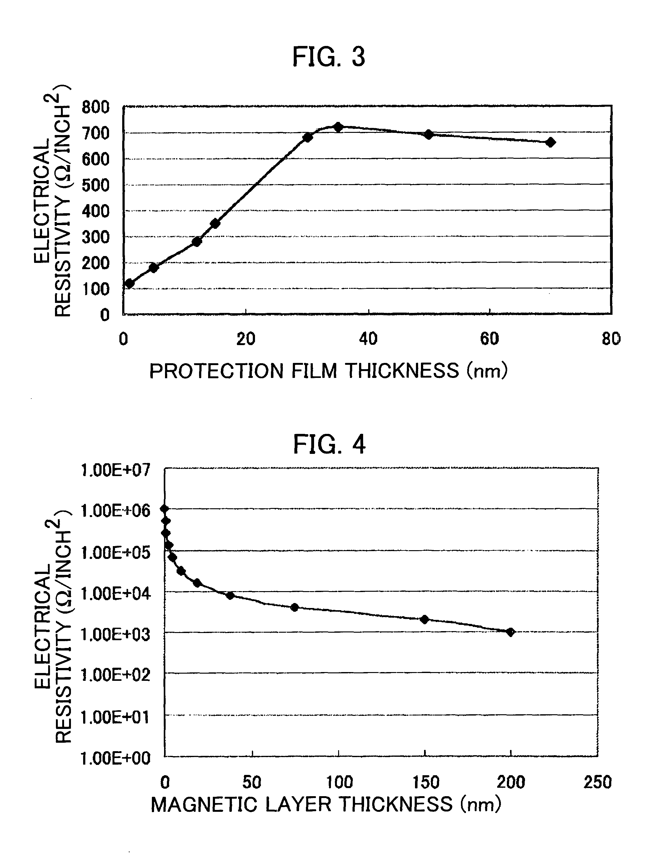
[0087]In example 1, a cleaning tape in which the particles 2 of the cleaning tape shown in FIG. 1 is removed and which has no surface protrusions 2 was prepared and measurements of the electrical resistivity are shown. FIG. 3 shows the relationship between the thickness of a carbon protection film serving as the inorganic protection film 4 and the electrical resistivity of the surface of the cleaning tape. When the thickness of the magnetic layer is set at 150 nm and the thickness of the carbon protection film is varied, the electrical resistivity is largest when the thickness of the carbon protection film is 35 nm.

[0088]With this particular thickness (35 nm) of the carbon protection film, measurement results of the electrical resistivity as a function of the thickness of the magnetic layer 3 are shown in FIG. 4. As shown in FIG. 4, electrical resistivity decreases as the magnetic layer 3 becomes thicker. Once the magnetic layer 3 becomes thinner than about 30 nm, electrical resisti...

example 2

[0091]In examples 2 to 4 below, as shown in FIG. 1, a carbon protection film was formed as the inorganic protection film 4 over the magnetic layer serving as the metal evaporated film 3. The carbon protection film was formed through sputtering. In example 2, the particle diameter of the particles 2 was 25 nm±5 nm, in example 3, the particle diameter of the particles 2 was made smaller (15 nm±5 nm), and in example 4, the particle diameter of the particles 2 was made larger (35 nm±5 nm).

[0092]Measurement results obtained with the cleaning tape of example 2 will be described below with reference to FIG. 5 to FIG. 9. FIG. 5 shows the results of analyzing the density of the surface protrusions (i.e., particle density) at which sufficient cleaning effects can be obtained when the thickness of the magnetic layer 3 is 50 nm and the thickness of the carbon protection film is 10 nm. The particles 2 of a particle diameter of 25 nm±5 nm were arranged on the non-magnetic substrate 1 to form prot...

example 3

[0111]Cleaning tapes were prepared in a manner similar to example 2 above except in that the particle diameter of the particles 2 was changed to 15 nm±5 nm and various measurements were taken. The tolerable range of head wear, the method of evaluating cleaning effects, and the like were the same as example 2 above. FIG. 10 to FIG. 14 show measurement results when particles of a particle diameter of 15 nm±5 nm were used.

[0112]FIG. 10 shows the results of analyzing the density of the surface protrusions that provide for sufficient cleaning effects when the thickness of the magnetic layer 3 is 50 nm and the thickness of the carbon protection film is 10 nm. According to the reference cleaning time mentioned above (about 10 seconds or shorter), sufficient cleaning effects were achieved when the density of the particles was 1000×104 per mm2 or higher. Also, as long as the density of the particles was 500×104 per mm2 or higher, the cleaning time was less than 20 seconds, and generally subs...


PUM


Abstract

There is provided a cleaning tape capable of attaining sufficient cleaning effects while preventing electrostatic discharge damage to magnetoresistive heads or changes in reproduced output due to excessive head wear. The cleaning tape includes a non-magnetic substrate 1, surface protrusions 6 formed on the non-magnetic substrate 1 with particles 2 having a particle diameter of 10 to 40 nm at a density of 300×104 to 5000×104 mm2, a metal evaporated film 3 (preferably an electrically conductive layer such as an alloy layer containing Co as a primary component, an Al layer or the like) having a thickness of 10 to 200 nm and an inorganic protection film 4 having a thickness of 3 to 50 nm formed on the metal evaporated film 3.

Description

CROSS REFERENCE TO RELATED APPLICATIONS[0001]The present document claims priority to Japanese Priority Document JP 2002-179112, filed in the Japanese Patent Office on Jun. 19, 2002, the entire contents of which are incorporated herein by reference to the extent permitted by law.BACKGROUND OF THE INVENTION[0002]1. Field of the Invention[0003]The present invention relates to a cleaning tape having a metal magnetic thin-film or a metal thin-film formed through vapor deposition.[0004]2. Description of the Related Art[0005]In the field of, for example, video tape recorders (VTRs), there are strong needs for improving recording density in order to obtain high quality images. The degradation of picture quality due to the accumulation of dirt on the surface across which the head slides becomes more prominent as the recording density becomes higher, the wavelength shorter and the tracks narrower. This makes cleaning tapes essential for general users to maintain the system in good conditions....

Claims


Application Information

Patent Timeline
IPC IPC(8): G11B5/41
CPCG11B5/41Y10S15/12
Inventor HONDA, HIDETOSHIKANOU, TAKASHIWAKO, HITOSHISEKINO, SATOSHIHIRATSUKA, RYOICHI
Owner SONY CORP
Why Eureka
Try Eureka