Thermalhead, method for manufacture of same, and printing device provided with same

a technology of thermal head and printing device, which is applied in the direction of printing, lamination ancillary operations, and thermal printing, can solve the problems of electrostatic charge, inability to produce a sufficiently advantageous effect, and inability to eliminate electrostatic charge, so as to prevent electrostatic discharge damage, reliable thermal head, and reliable printing device

Inactive Publication Date: 2009-07-09
TDK CORPARATION
View PDF3 Cites 8 Cited by
  • Summary
  • Abstract
  • Description
  • Claims
  • Application Information

AI Technical Summary

Benefits of technology

[0021]According to the present invention, the protective layer is electrically connected to the metallic mound. This allows electrostatic charge accumulated on the surface of the protective layer during printing to be dissipated to ground. This in turn prevents electrostatic discharge damage from occurring in the heat elements or the bonding pad portion. This makes it possible to provide a reliable thermal head and a reliable printing device provided with the thermal head.
[0022]From another viewpoint, the protective layer and the bonding pad portion are spaced apart from each other by a predetermined distance, thereby preventing electrostatic discharge damage accumulated in the protective layer from causing electrostatic discharge damage in the bonding par portion. This makes it possible to provide a reliable thermal head, a method for manufacture of such thermal head, and a printing device provided with such thermal head.

Problems solved by technology

However, the electrostatic charge is thereby not eliminated.
This creates the problem of failing to produce a sufficiently advantageous effect in the case of high-speed printing, which easily generates electrostatic charge.
In addition, because the electrostatic charge generated by the conductive film and the recording medium sliding against each other is merely displaced, and not eliminated, the displaced electrostatic charge could still cause electrostatic discharge damage.
In particular, the disclosures in Patent Documents 1 to 3 do not teach how to sufficiently prevent electrostatic discharge damage from occurring in the bonding pad portion.
This makes it difficult to adopt the technique in view of cost and yield.

Method used


Image

  • Thermalhead, method for manufacture of same, and printing device provided with same
  • Thermalhead, method for manufacture of same, and printing device provided with same
  • Thermalhead, method for manufacture of same, and printing device provided with same

Examples


first embodiment

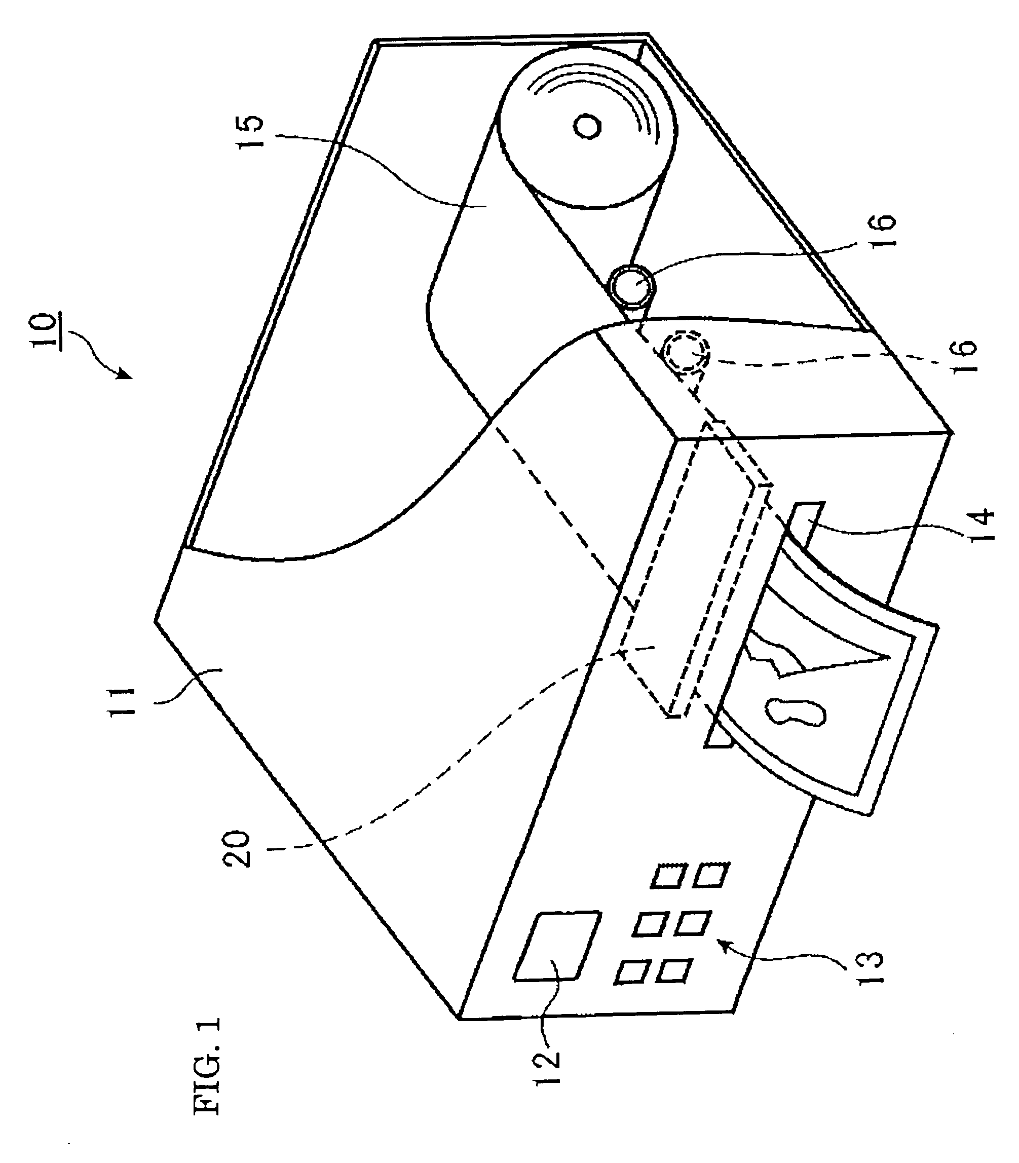
[0044]FIG. 1 is a schematic view of a printing device 10 equipped with a thermal head according to an embodiment of the present invention. The printing device 10 has a hexahedral casing 11. The front face of the casing 10 is provided with a liquid crystal panel 12, an input keyboard 13, and a paper outlet 14. The casing 11 accommodates a thermal paper 15. The paper 15 is wound into a roll. The front portion of the thermal paper 15 is supported by plural transport rollers 16 so as to be positioned ahead of a paper outlet 14. The casing 11 incorporates a thermal head unit 20. The unit 20 includes a thermal head. The unit 20 is located above the paper 15. The unit 20 produces characters, images, etc., on the paper 15 by heating the paper 15 for color development. This is a printing operation performed by the unit 20. After printing, the paper 15 is ejected from the outlet 14.

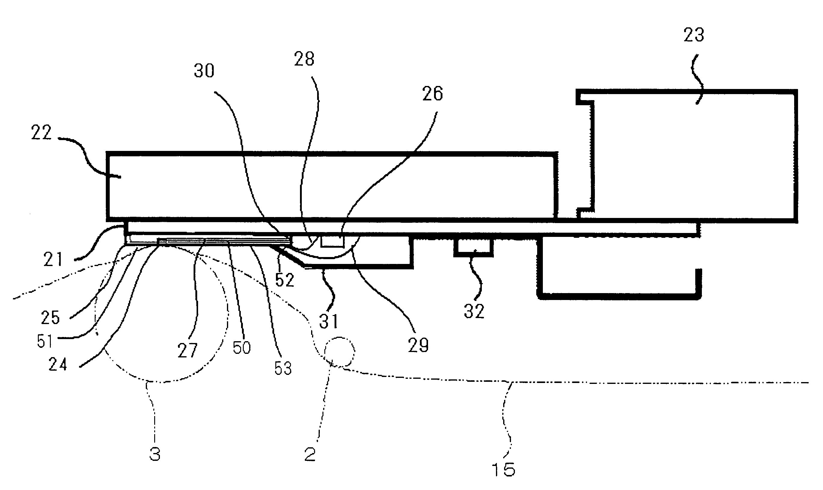
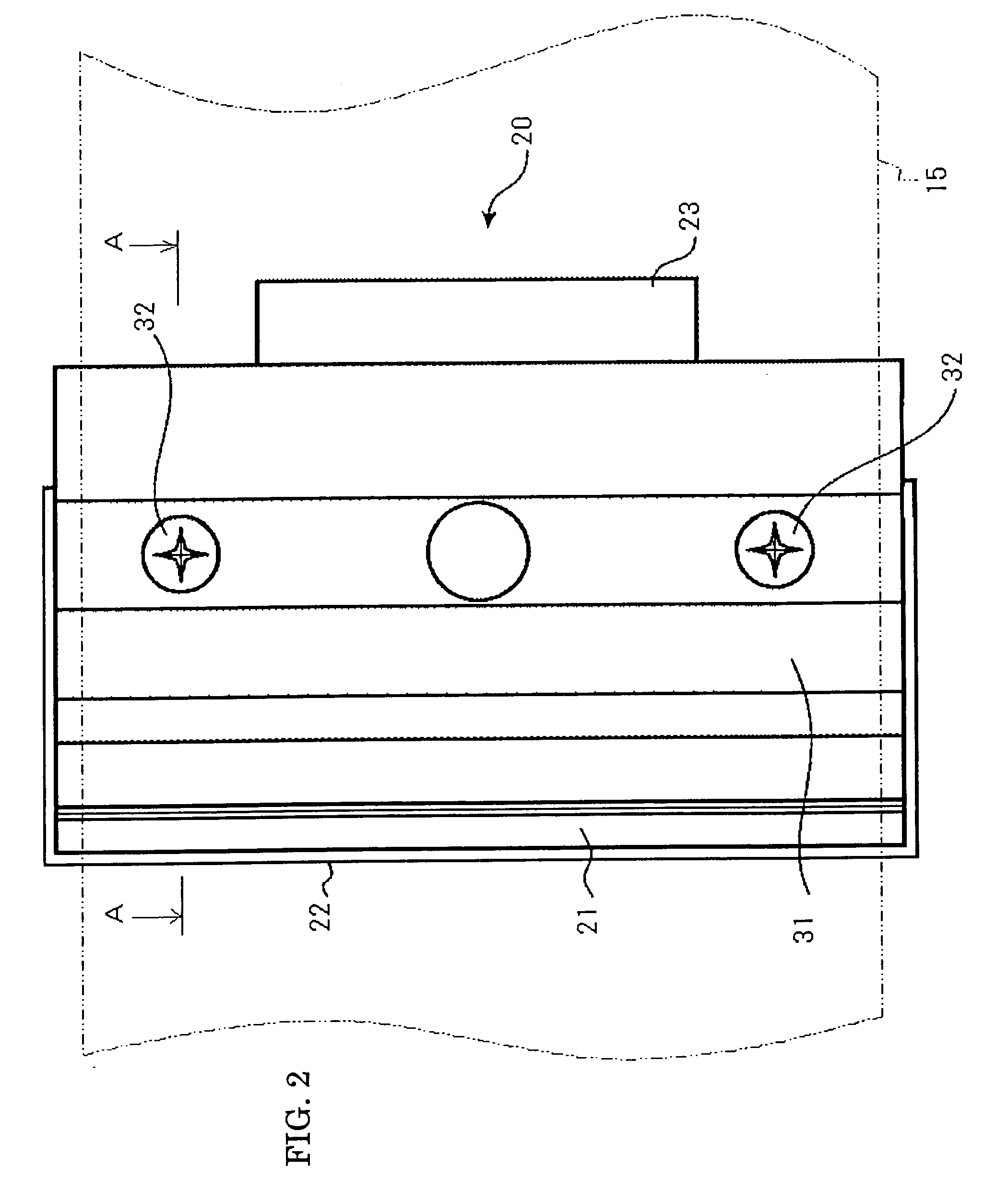
[0045]FIG. 2 is a plan view of the thermal head unit 20 as seen from below. FIG. 3 is a cross sectional view of ...

second embodiment

[0070]FIG. 14 is a partial cross sectional view of a thermal head according to the second embodiment of the present invention. FIG. 14 corresponds to FIG. 6(a) referred to in connection with the first embodiment. The second embodiment involves increasing the electric conductivity of the surface layer 51d of the protective layer 51. Except for this, the second embodiment is the same as the first embodiment. The manufacture method of the first embodiment includes the step S15. This step involves stacking the layer 51 on the substrate 60. In the second embodiment, when performing this stacking, the layer 51 is doped with an adequate amount of an adequate impurity. This aims to realize the following (1) and (2). (1) The layer 51 contains an electrically insulating region defined by a predetermined thickness measured from the interface 50c of the insulating layer 50. (2) The layer 51 contains also an electrically conductive region defined by a predetermined depth measured from the upper ...

third embodiment

[0071]FIG. 15 is a partial cross sectional view of a thermal head according to the third embodiment of the present invention. FIG. 15 corresponds to FIG. 6(a) referred to in connection with the first embodiment. The third embodiment involves increasing the electric conductivity of the middle layer 51e of the protective layer 51. Except for this, the third embodiment is the same as the first embodiment. The manufacture method of the first embodiment includes the step S15. This step involves stacking the layer 51 on the substrate 60. In the third embodiment, when performing this stacking, the layer 51 is doped with an adequate amount of an adequate impurity. This aims to realize the following (1), (2), and (3). (1) The layer 51 contains an electrically insulating region defined by a predetermined thickness measured from the interface 50c of the insulating layer 50. (2) The layer 51 contains also another electrically insulating region defined by a predetermined depth measured from the ...


PUM

PropertyMeasurementUnit
distanceaaaaaaaaaa
distanceaaaaaaaaaa
distanceaaaaaaaaaa

Abstract

The object of the invention is to provide a reliable thermal head designed to prevent electrostatic discharge damage from occurring in the bonding pad portion due to the protective layer being electrostatically charged; a method for manufacture of the thermal head; and a printing head for the thermal head.
The present invention relates to the thermal head including: the heat elements 24 provided on the substrate 25; the wiring patterns 27 and 47 for applying electric power to the heat elements; and the bonding pad portion 52; wherein the heat elements 24 being covered by the protective layer 5; wherein the substrate 25 is secured on the metallic mount 21; and wherein the protective layer 51 is electrically connected to the mount 21.

Description

TECHNICAL FIELD[0001]The present invention relates to a thermal head, a method for manufacture of the thermal head, and a printing device provided with the thermal head. In particular, the present invention relates to: a thermal head to be mounted in various printing devices for business or consumer use; a method for manufacture of such thermal head; and a printing device mounted with such thermal head.BACKGROUND OF THE INVENTION[0002]There is a type of thermal heads used for thermal recording in various types of printing devices, such as the rewritable printers, the card printers, the video printers, the barcode printers, the label printers, the facsimile machines, and the ticket vending machines. This type of thermal heads heats the recording medium to a predetermined temperature to print information thereon or erase information therefrom. More specifically, a thermal head of this type is designed to selectively apply an electric potential to at least one heat element linearly dis...

Claims


Application Information

Patent Timeline
Patent Type & Authority Applications(United States)
IPC IPC(8): B41J2/335B32B38/10B41M5/26
CPCB41J2/3353B41J2/3359B41J2/33545
Inventor YAMADA, HIROSHIUCHIDA, KAZUHITOIINO, TADASHIANDOH, SUGURUMIYASHITA, HAYATO
Owner TDK CORPARATION
Why Eureka
Try Eureka