Display device

Active Publication Date: 2012-05-17
JAPAN DISPLAY INC
View PDF2 Cites 12 Cited by
  • Summary
  • Abstract
  • Description
  • Claims
  • Application Information

AI Technical Summary

Benefits of technology

[0016]According to the present invention, the electrostatic discharge damage can be prevented with a simple

Problems solved by technology

In a display device including a plurality of pixel circuits formed on a planar substrate, a short circuit may occur by static electricity during manufacturing, and product failure may occur in some cases (hereinafter, this phenomenon is referred to as electrostatic discharge damage).
In the manufacturing s

Method used


Image

  • Display device
  • Display device
  • Display device

Examples


Embodiment Construction

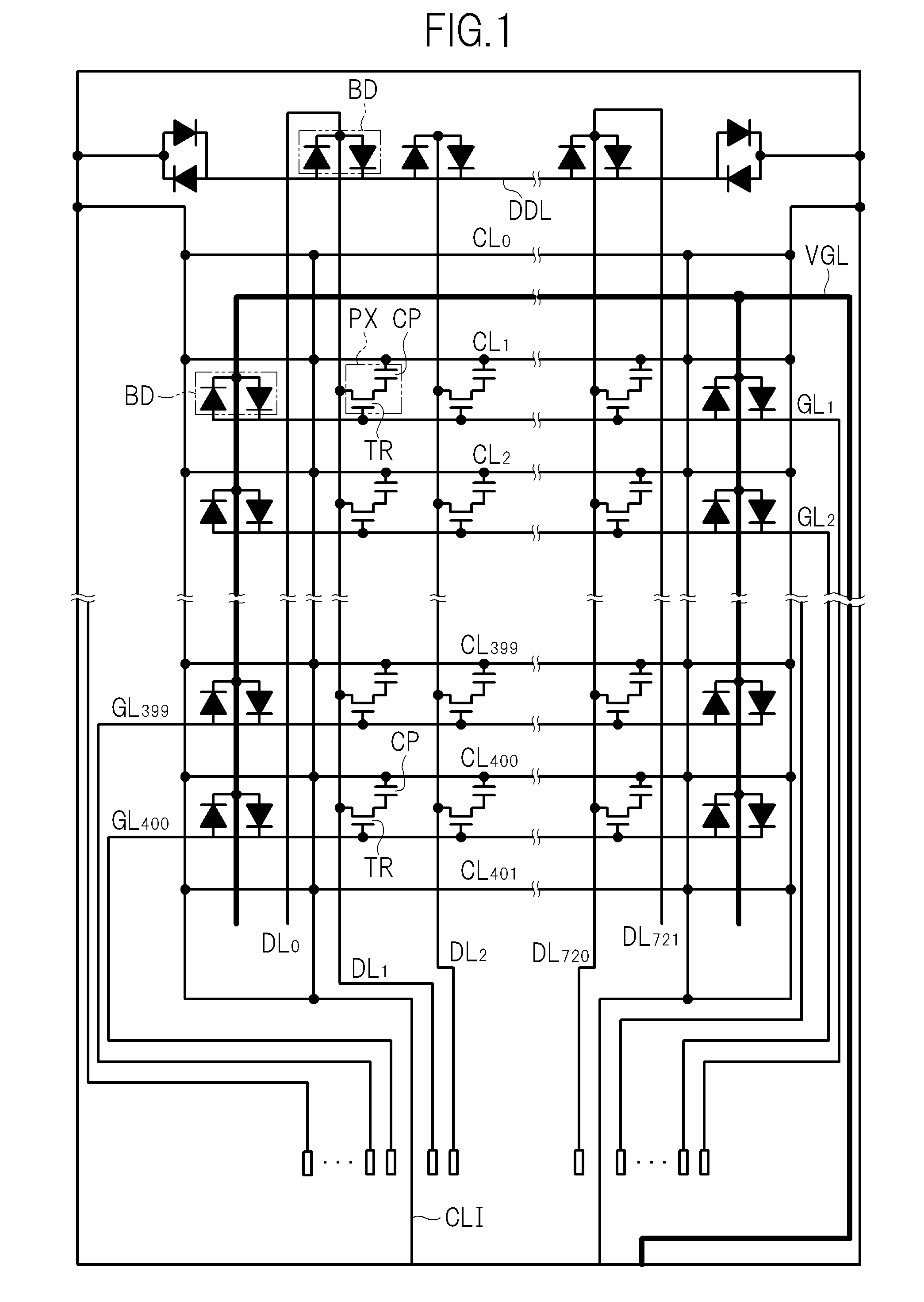
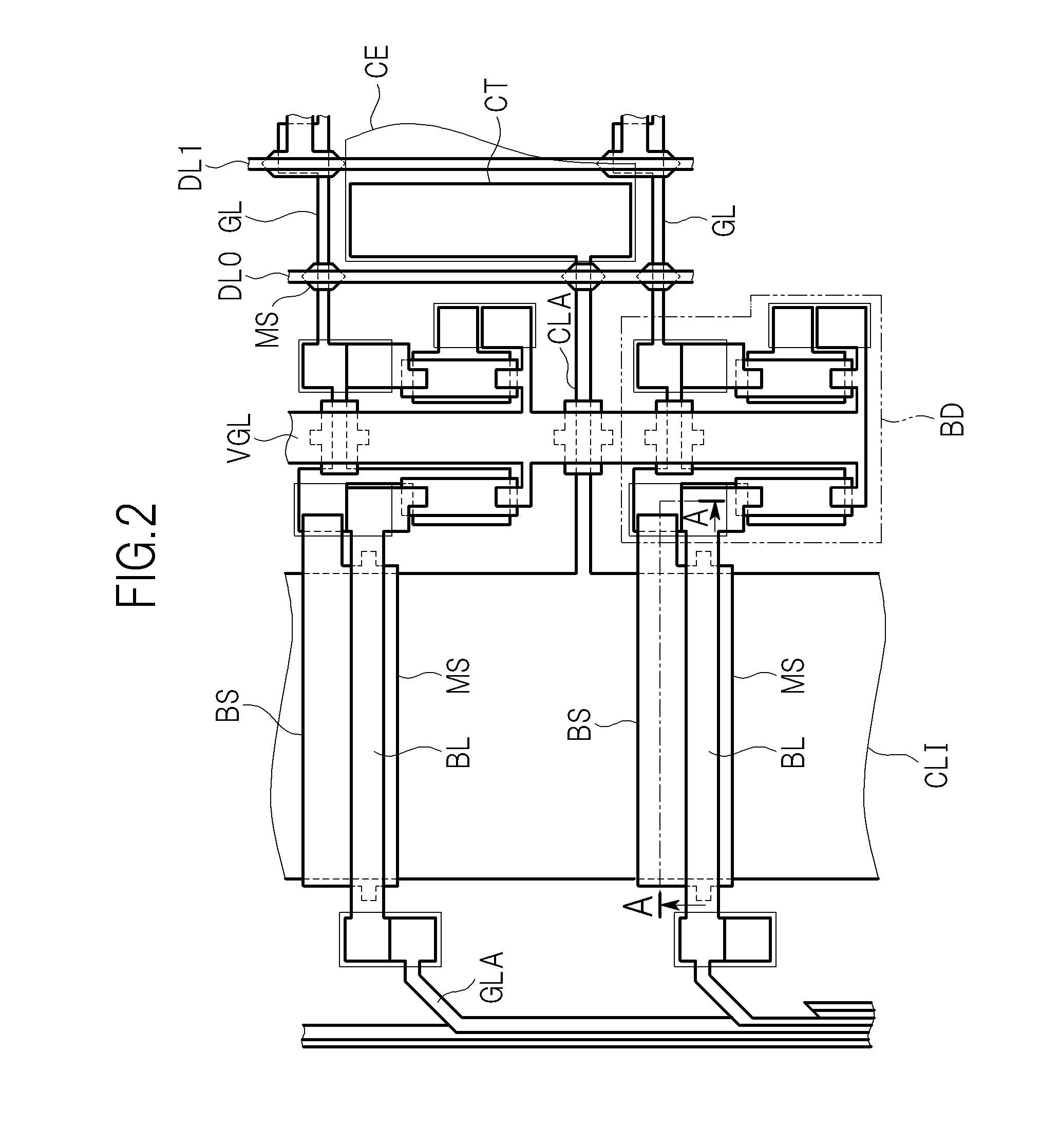
[0024]Hereinafter, an embodiment of the present invention is described with reference to the drawings. Throughout the description, the same reference symbols are attached to components having the same function, and redundant description thereof is omitted. Hereinafter, description is made of a case where the present invention is applied to an in-plane-switching (IPS) type liquid crystal display device as an example of a display device.

[0025]The liquid crystal display device according to the embodiment of the present invention includes a liquid crystal display panel. The liquid crystal display panel includes an array substrate, a filter substrate (also referred to as counter substrate), which is opposed to the array substrate and includes a color filter, a liquid crystal material sealed in a region sandwiched between both the substrates, and a driver integrated circuit mounted on the array substrate. The array substrate and the filter substrate are each an insulating substrate such a...


PUM


Abstract

A display device includes an insulating substrate; a first conductive layer in which a first signal line and a second signal line are formed on the insulating substrate; an insulating layer provided in an upper layer of the first conductive layer; and a semiconductor layer, which is provided in an upper layer of the insulating layer, and in which a semiconductor film, which overlaps the first signal line and the second signal line in plan view, is formed.

Description

CROSS-REFERENCE TO RELATED APPLICATION[0001]The present application claims priority from Japanese application JP 2010-257036 filed on Nov. 17, 2010, the content of which is hereby incorporated by reference into this application.BACKGROUND OF THE INVENTION[0002]1. Field of the Invention[0003]The present invention relates to a display device, and more particularly, to a display device including a plurality of pixel circuits provided on a substrate.[0004]2. Description of the Related Art[0005]In a display device including a plurality of pixel circuits formed on a planar substrate, a short circuit may occur by static electricity during manufacturing, and product failure may occur in some cases (hereinafter, this phenomenon is referred to as electrostatic discharge damage). For example, as a measure for preventing the electrostatic discharge damage in a liquid crystal display device, a bidirectional diode is provided between wiring lines which have possibility of being short-circuited.[0...

Claims


Application Information

Patent Timeline
IPC IPC(8): G09G3/00
CPCG09G3/3648G09G2330/04G09G2300/0426
Inventor NAKAYASU, YOUZOU
Owner JAPAN DISPLAY INC
Why Eureka
Try Eureka