
Arbiter circuit and method of carrying out arbitration

a technology of arbitrator circuit and circuit, which is applied in the field of arbitrator circuit, can solve the problems of destroying data carried by packets, significant increase in fabrication cost, and conventional packet exchangers without efficient accumulating algorithms, etc., and achieves efficient accumulating plurality, low process capacity, and increased capacity of packet exchangers.

Inactive Publication Date: 2006-02-14
JUMIPER NETWORKS INC
View PDF15 Cites 19 Cited by
  • Summary
  • Abstract
  • Description
  • Claims
  • Application Information

AI Technical Summary

Benefits of technology

The present invention provides a method and an arbiter circuit for carrying out arbitration in a packet exchanger with increased capacity. The method includes carrying out a plurality of sequences in a predetermined order, with each sequence including a basic process for an input buffer and an output port. The method allows for the accumulation of packets in the input buffer and efficient accumulation of packets in the output port. The method also allows for the output of packets through different output ports at different times, and allows for the selection of input buffers and output ports based on their priority. The arbiter circuit includes input and output buffers, and a processor for carrying out the basic processes. The method and circuit can be used in both input and output sequential arbitration.

Problems solved by technology

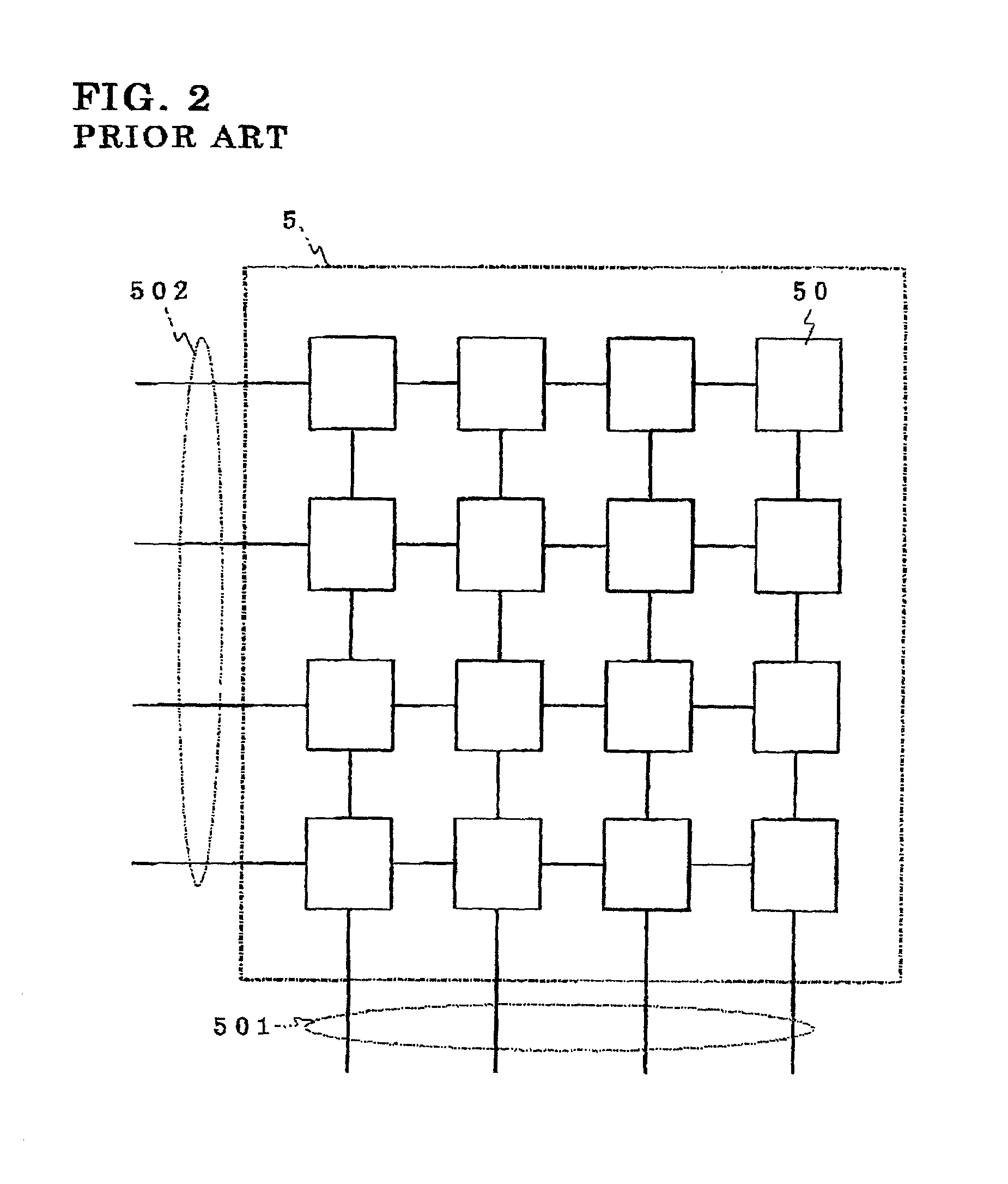
The packet switch 5 illustrated in FIG. 2 is accompanied with a problem that when a plurality of the input ports concurrently transmit packets to a specific output port, packets would make collision with one another, resulting in destruction of data carried by the packets.
Accordingly, if the packet exchanger is designed to have an increased capacity, the arbiter circuit carrying out the arbitration has to be designed to have a process capacity thereof multiplied by X in rate, resulting in a significant increase in fabrication cost.
In addition, even if a plurality of classes classified by its priority, there the conventional packet exchanger does not have an algorithm for efficiently accumulating the classes.
However, the above-mentioned problems remain unsolved even in the above-mentioned Publications.

Method used


Image

  • Arbiter circuit and method of carrying out arbitration
  • Arbiter circuit and method of carrying out arbitration
  • Arbiter circuit and method of carrying out arbitration

Examples


first embodiment

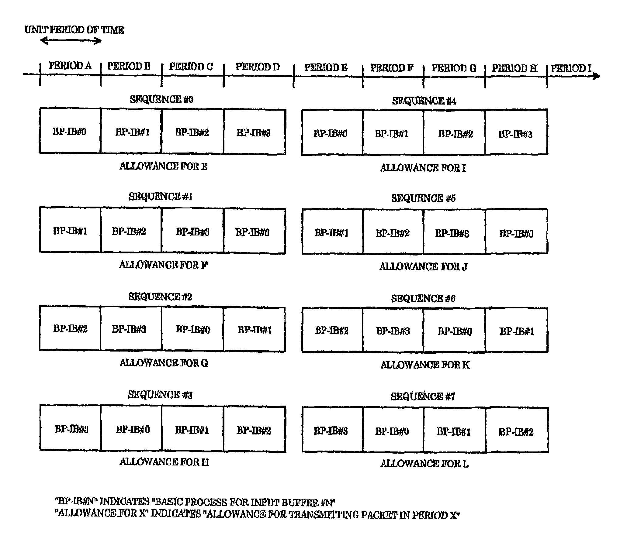
[0118]FIG. 6 is a timing chart showing a timing at which each of sequences is carried out in the input sequential arbitration in the method of carrying out arbitration in a packet exchanger, in accordance with the

[0119]It is assumed in the first embodiment that a packet exchanger has four input and output ports.

[0120]In the first embodiment, four sequences equal in number to the input and output ports are concurrently carried out. In each of the sequences, an allowance to transmit a packet at different times is made. In the first embodiment, as illustrated in FIG. 6, an allowance to transmit a packet at a time E is made in a first sequence #0, an allowance to transmit a packet at a time F is made in a second sequence #1, an allowance to transmit a packet at a time G is made in a third sequence #2, and an allowance to transmit a packet at a time H is made in a fourth sequence #3.

[0121]After the first to fourth sequences #0 to #3 have been completed, next four sequences #4 to #7 concu...

second embodiment

[0219]FIG. 18 is a timing chart showing a timing at which each of sequences is carried out in the input sequential arbitration in the method of carrying out arbitration in a packet exchanger, in accordance with the

[0220]In the second embodiment, after a first sequence has been completed, a second sequence is carried out. In the second sequence, the basic processes are carried out in an order just opposite to an order in which the basic processes are carried out in the first sequence.

[0221]For instance, in the first sequence #0, the basic processes are carried out for the input buffers #0, #1, #2 and #3 in this order. In contrast, in the fifth sequence #4 carried out just after the first sequence #0, the basic processes are carried out in an order opposite to the order in the first sequence #0. Specifically, the basic processes are carried out for the input buffers #0, #3, #2 and #1 in this order.

[0222]This arrangement prevents input buffers having a smaller number from preferentiall...

third embodiment

[0231]FIG. 20 is a timing chart showing a timing at which each of sequences is carried out in the input sequential arbitration in the method of carrying out arbitration in a packet exchanger, in accordance with the

[0232]In the third embodiment, the sequences #0 to #7 are grouped into a first group including the sequences #0 to #3 and a second group including the sequences #4 to #7, and an intermission is arranged between the first and second groups.

[0233]Specifically, the sequences #0 to #3 are first concurrently carried out. Then, after a unit period of time has been passed, the sequences #4 to #7 are concurrently carried out. In the sequences #0 to #7, an allowance to transmit a packet at different time is made.

[0234]In accordance with the third embodiment, a signal indicative of information relating to vacant output ports can be transmitted through the first to fourth unit modules 31 to 34 in a unit period of time as an intermission.

[0235]In the third embodiment, though a sequenc...


PUM


Abstract

A method of carrying out arbitration in a packet exchanger including an input buffer temporarily storing a packet having arrived at an input port, and a packet switch which switches a packet between a specific input port and a specific output port, includes the steps of (a) concurrently carrying out a first plurality of sequences in each of the sequences basic processes for at least one of the input buffer and the output port are carried out in a predetermined order, and (b) making an allowance in each of the sequences for packets to be output through output ports at different times from one another.

Description

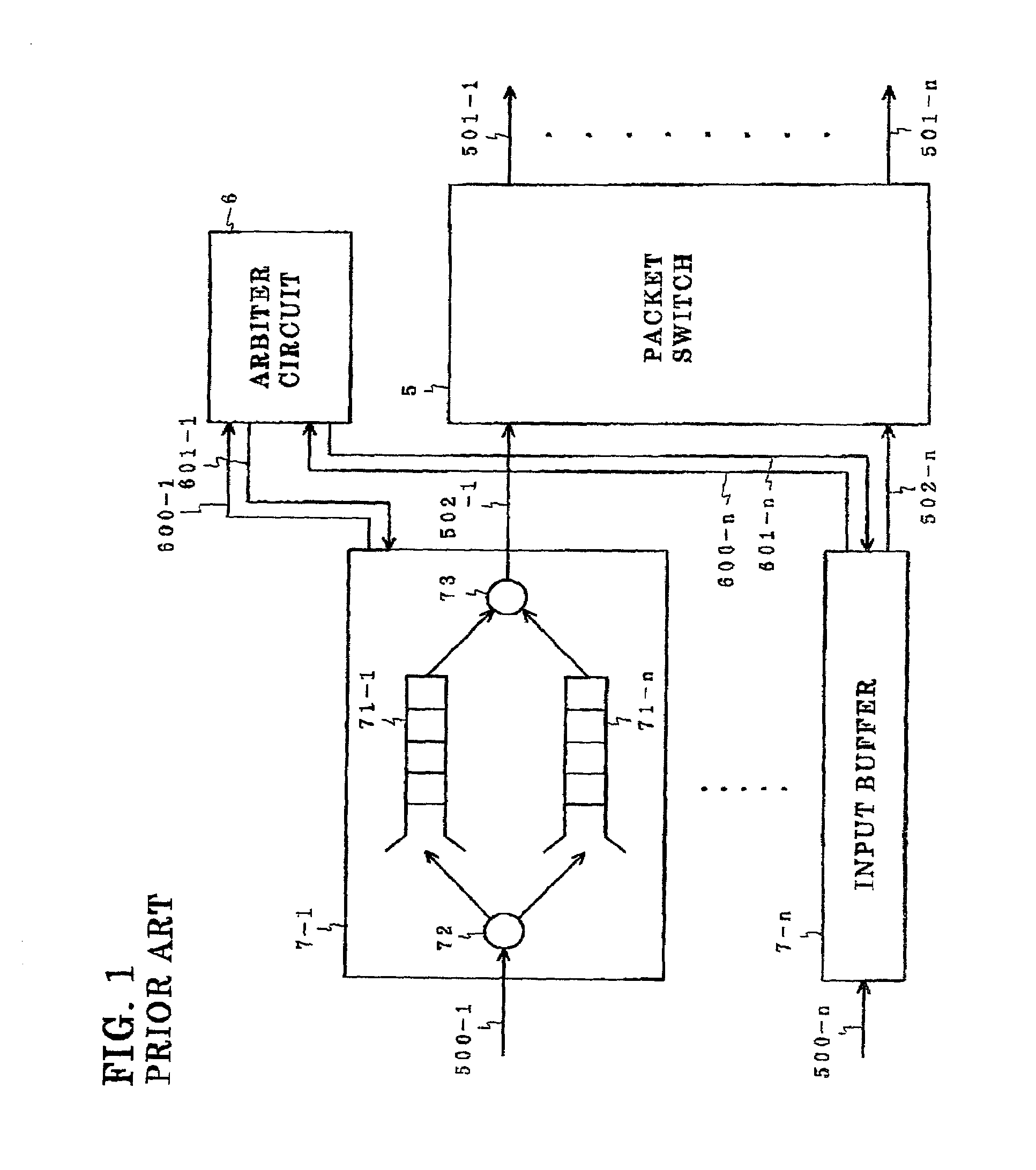
BACKGROUND OF THE INVENTION[0001]1. Field of the Invention[0002]The invention relates to an arbiter circuit used in a packet exchanger, and more particularly to an arbiter circuit used in a packet exchanger which switches a packet between a specific input port and a specific output port by virtue of packet communication technique such as asynchronous transfer mode (ATM). The invention relates further to a method of carrying out arbitration in such a packet exchanger.[0003]2. Description of the Related Art[0004]FIG. 1 is a block diagram of a conventional packet exchanger.[0005]The illustrated packet exchanger is comprised of input ports 500-1 to 500-n, output ports 501-1 to 501-n, a packet switch 5 which switches a packet between the input ports 500-1 to 500-n and the output ports 501-1 to 501-n, input buffers 7-1 to 7-n temporarily accumulating packets having arrived at the input ports 500-1 to 500-n, an arbiter circuit 6, and input highways 502-1 to 502-n connecting the input buffe...

Claims


Application Information

Patent Timeline
Patent Type & Authority Patents(United States)
IPC IPC(8): H04L12/56H04L47/6275H04Q11/04
CPCH04L47/34H04Q11/0478H04L2012/5679
Inventor SHINOHARA, MASAYUKI
Owner JUMIPER NETWORKS INC
Learn More