
Spatio-temporal joint filter for noise reduction

a spatial-temporal joint and noise reduction technology, applied in the field of noise reduction filters, can solve the problems of degrading image to viewers, negative effects on image signal processing, and video signals initially received from video cameras and transmitted through channels unavoidably contain noise signals, so as to achieve aggressive noise reduction and eliminate temporal flickers

Inactive Publication Date: 2006-02-14
LG ELECTRONICS INC
View PDF3 Cites 42 Cited by
  • Summary
  • Abstract
  • Description
  • Claims
  • Application Information

AI Technical Summary

Benefits of technology

[0019]An object of the present invention is to provide a joint spatio-temporal noise-reduction filter that preserves edge / detail regions of an image, performs a aggressive noise reduction on flat regions, and eliminates temporal flickers occurred between adjacent image frames by combining more than one noise reduction filters having various characteristics.

Problems solved by technology

In general, video signals initially received from a video camera and transmitted through a channel unavoidably contain noise signals.
A noise signal added to a video signal provides a degraded image to viewers and has negative effects on the image signal processes.
Unfortunately, some of the edge or detail region of an image may be removed when an every region of the image goes through the aggressive noise reduction process.
This also degrades the image quality.
In other words, an aggressive noise reduction performed to achieve the first objective will result in losing some of the edge / detail region of an image.
On the other hand, an insufficient degree of noise reduction for achieving the second object will not satisfactorily remove the noise signal for the first objective.
However, they include the structural limitations due to their two dimensional characteristics and do not eliminate the temporal flicker mentioned earlier.
If the support regions of those filters are expanded to three dimensions, the noise reduction performance may be deteriorated, resulting the blurred images.
However, it introduces other problems.
First, the noise reduction performance of the motion adaptive noise reducer depends the accuracy of motion information.
However, the noise included in the image makes it difficult to obtain the accurate information.
Second, the result of the noise reduction performed on a region having motions is not satisfactory.

Method used


Image

  • Spatio-temporal joint filter for noise reduction
  • Spatio-temporal joint filter for noise reduction
  • Spatio-temporal joint filter for noise reduction

Examples


Embodiment Construction

[0029]Reference will now be made in detail to the preferred embodiments of the present invention, examples of which are illustrated in the accompanying drawings.

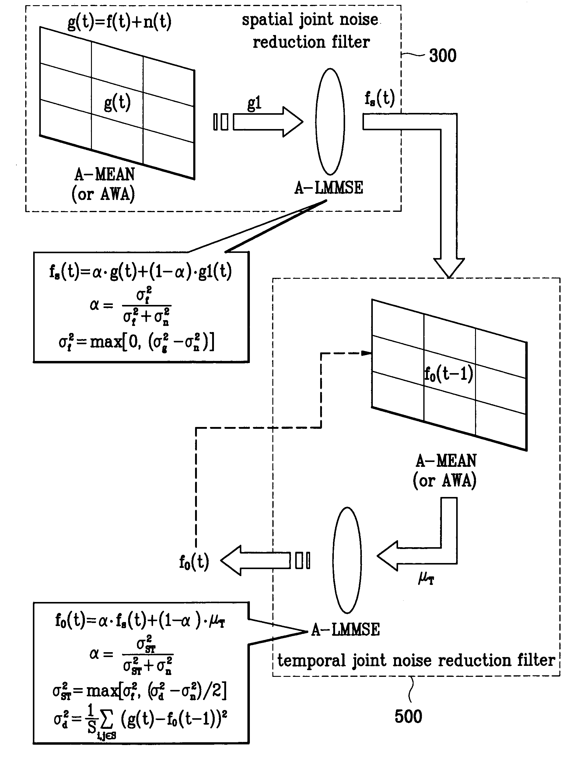
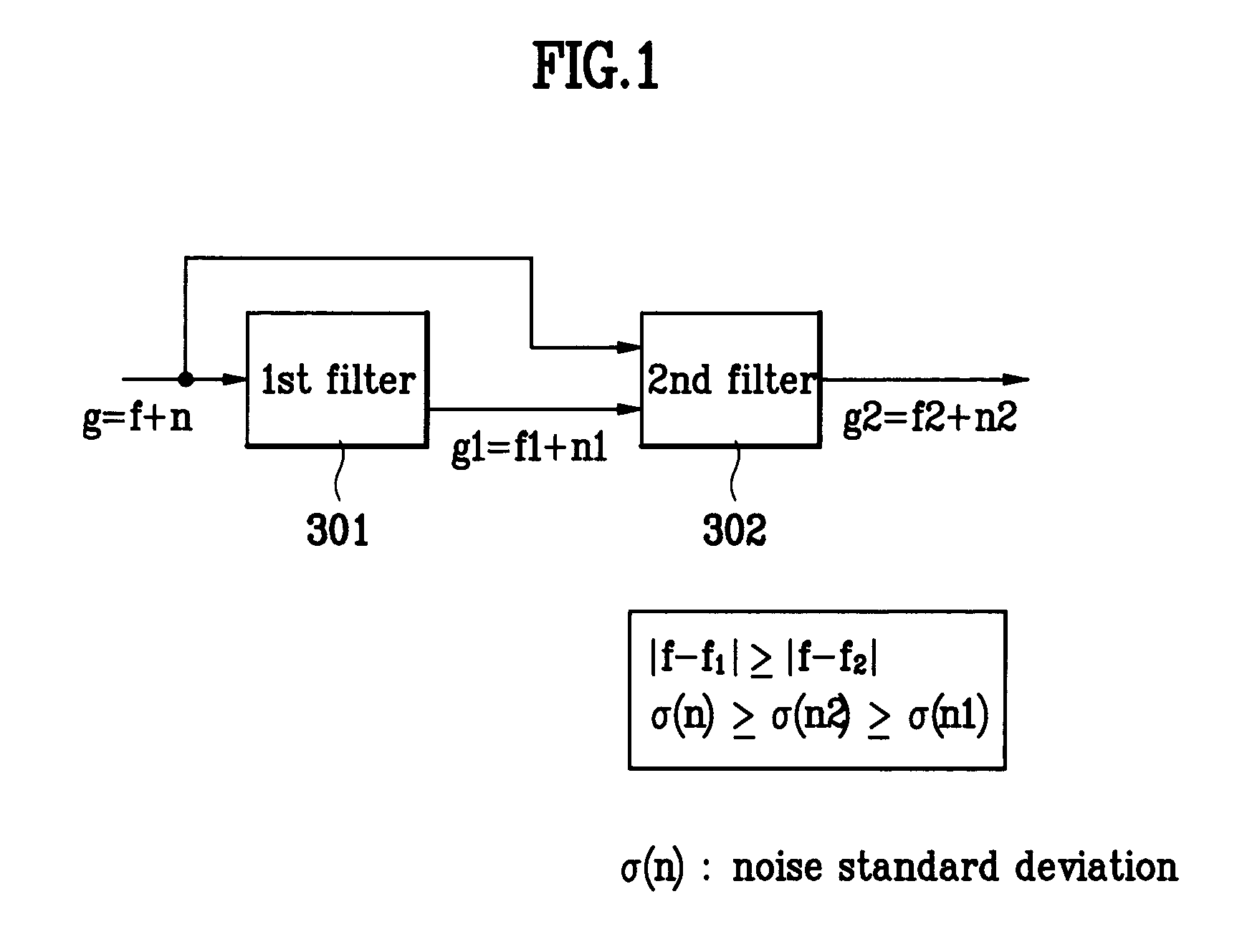
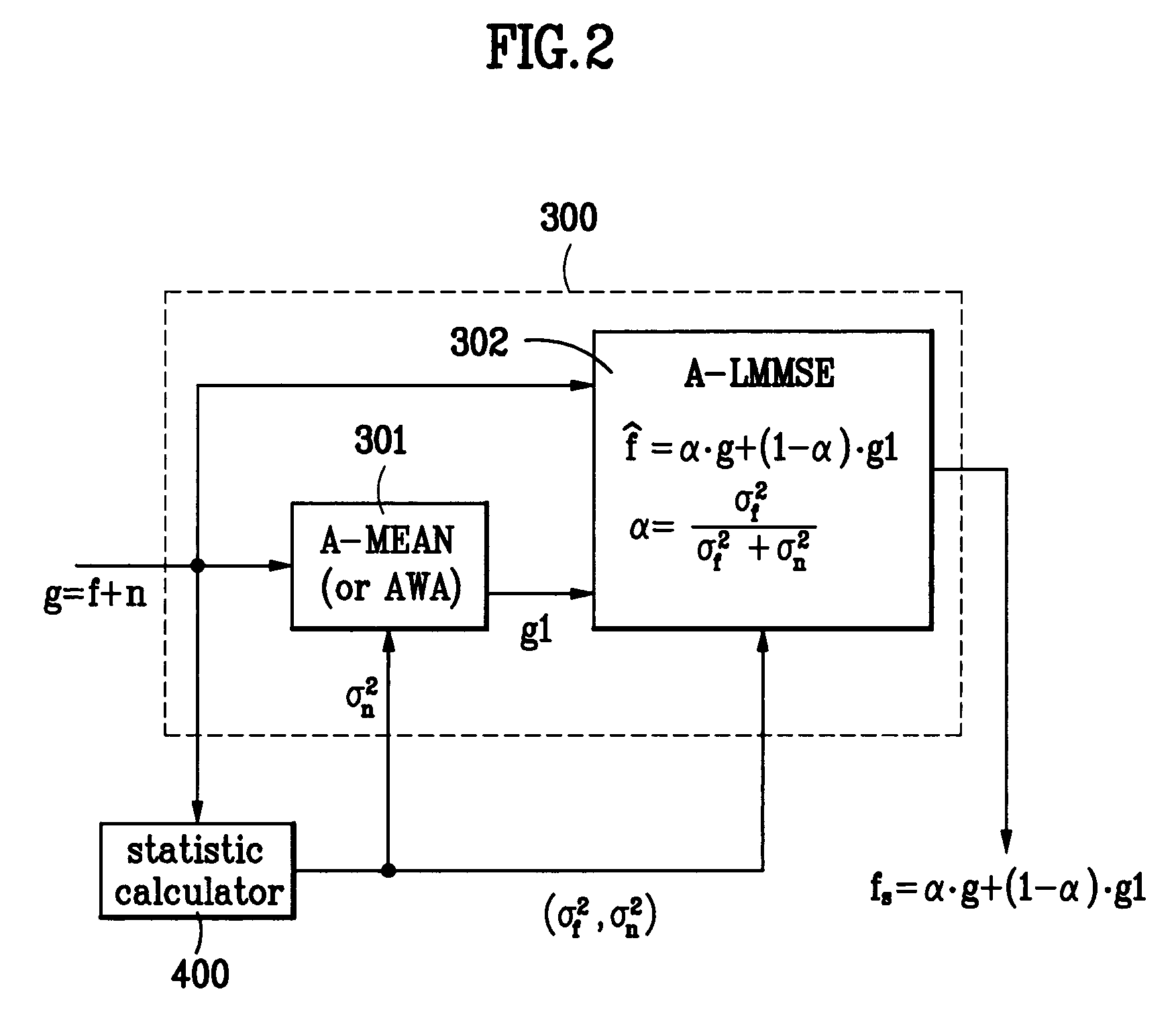
[0030]The present invention relates to a joint spatio-temporal noise-reduction filter that combines an AWA (or A-MEAN) filter characteristic together with an A-LMMSE filter characteristic. FIG. 1 illustrates a brief structure of a spatial joint noise-reduction filter according to the present invention. It includes a first filter (301) filtering a input signal g (f+n) and generating g1 (f1+n1); and a second filter (302) filtering g (f+n) and g1 (f1+n1) and generating g2 (f2+n2). According to the present invention, f2 is closer to the original input signal f than f1: |f−f1|≧|f−f2|. In addition, the level of noise reduction of the first filter (301) is less than that of the second filter (302). The variances of the noises are such that σ(n)≧σ(n2)≦σ(n1).

[0031]The complexity and performance of the joint filter according to the pr...


PUM


Abstract

A spatio-temporal joint filter and a spatial joint filter for noise reduction are disclosed. The spatio-temporal joint filter includes a spatial joint filter including the first and second sub filters having different characteristics and includes a temporal joint filter. When the present invention is adequately used, an edge / detail region of an image is well preserved, an aggressive noise reduction is performed on a flat region, and the temporal flicker problems are eliminated. Additionally, it has an intrinsic motion compensation effect by using the spatio-temporal correlation between the adjacent frames.

Description

BACKGROUND OF THE INVENTION[0001]1. Field of the Invention[0002]The present invention relates to noise reduction filters eliminating a noise signal included in an image signal, and more particularly, to a spatio-temporal and spatial joint noise reduction filters that combines more than one filters having various filter characteristics.[0003]2. Background of the Related Art[0004]In general, video signals initially received from a video camera and transmitted through a channel unavoidably contain noise signals. A noise signal added to a video signal provides a degraded image to viewers and has negative effects on the image signal processes. Therefore, signal receivers or any other necessary devices have a noise reduction process to avoid such problems. Some of the objectives need to be taken into consideration are as follows.[0005](1) Noise Elimination:A noise signal should be eliminated so that a clear image can be provided. Particularly, an aggressive noise reduction control is nece...

Claims


Application Information

Patent Timeline
IPC IPC(8): G06K9/40H04N5/213G06T5/20
CPCG06T5/20Y10S348/909Y10S348/91H04N5/213
Inventor HONG, SUNG HOON
Owner LG ELECTRONICS INC
Learn More