Demolition equipment having universal tines and a method for designing a universal tine

a technology of demolition equipment and universal tines, which is applied in the direction of load-engaging elements, borehole/well accessories, constructions, etc., can solve the problems of insufficient consideration of how the geometry of the claw tine changes, the most efficient way of addressing, and the device may be impractical and expensiv

Inactive Publication Date: 2006-02-21
RAMUN JOHN R
View PDF35 Cites 12 Cited by
  • Summary
  • Abstract
  • Description
  • Claims
  • Application Information

AI Technical Summary

Problems solved by technology

To date, there has not been sufficient consideration given to how changes in the geometry of the claw tine can effect the operation.
This is not the most efficient way of addressing the problem and the resulting device may be impractical and expensive.
Additionally, the existing claw tines have been designed to be associated with a given piece of construction equipment and were not adapted for other uses.
Finally, the attachment systems utilized in existing claw tines were not efficient and many required additional machining in order to get the claw tines to fit on an existing bucket or other existing component structure.

Method used


Image

  • Demolition equipment having universal tines and a method for designing a universal tine
  • Demolition equipment having universal tines and a method for designing a universal tine
  • Demolition equipment having universal tines and a method for designing a universal tine

Examples


Embodiment Construction

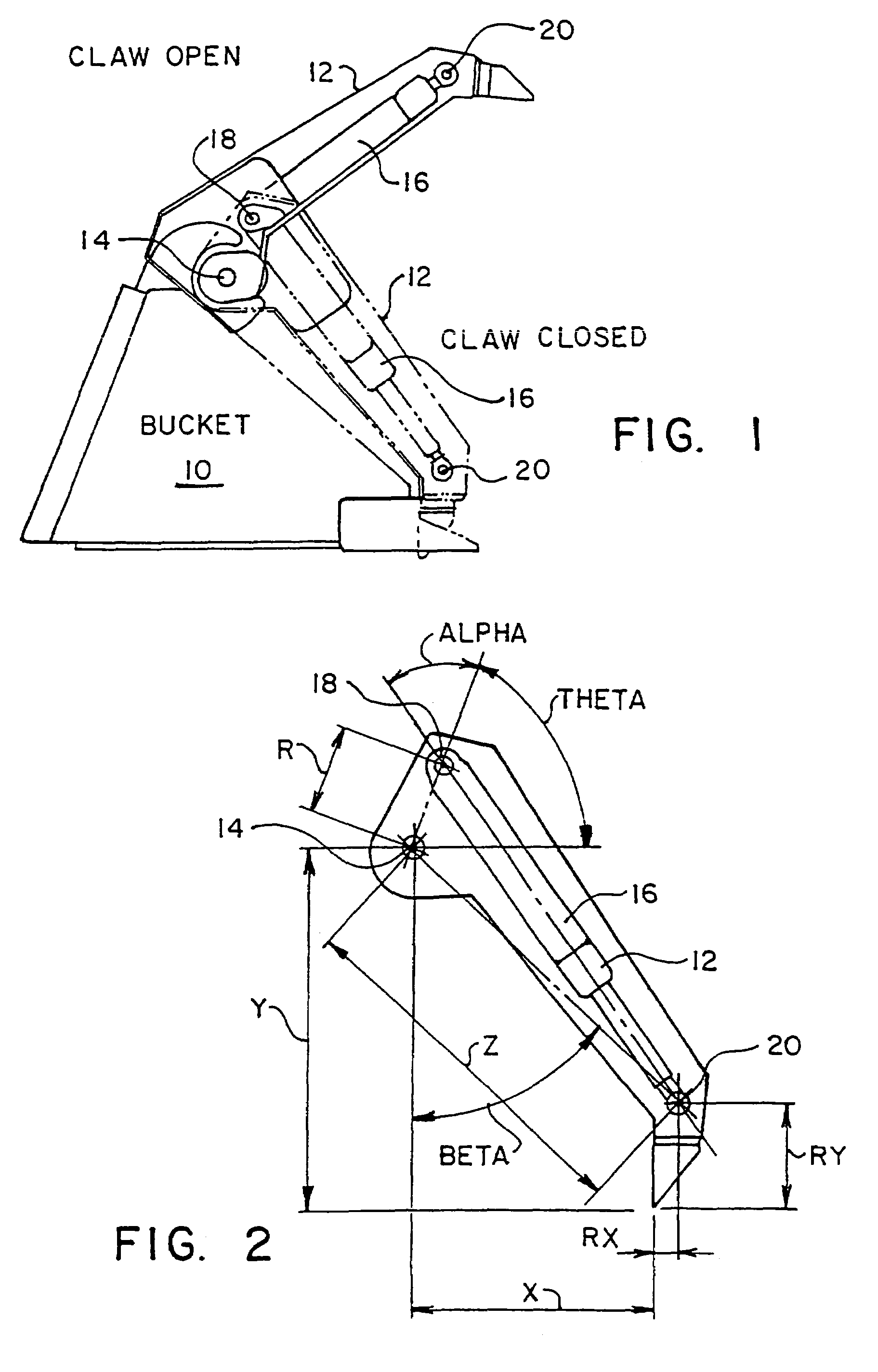
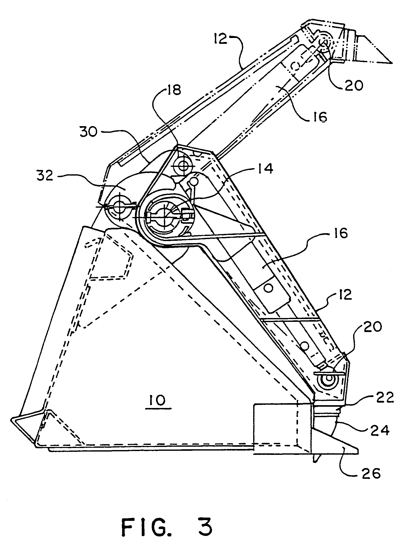
[0051]FIG. 1 schematically illustrates a bucket 10 with a claw structure according to the present invention coupled thereto. The claw structure includes at least one claw tine 12 pivotally attached to the bucket 10 for movement about a pivot point 14. A hydraulic cylinder 16 is positioned generally within the claw tine 12 and has one end thereof pinned to the bucket 10 at a fixed end 18 and secured to the claw tine 12 at a cylinder rod end 20. The claw tine 12 of the present invention encloses and protects the hydraulic cylinder 16. The hydraulic cylinder 16 provides power for moving the claw tine 12 between the open and closed positions illustrated in FIG. 1.

[0052]The specific geometry of the claw tine 12 according to the present invention allows the claw tine 12 to be easily adapted for a wide variety of construction equipment as will described hereinafter. FIG. 2 better illustrates the important linkage parameters associated with the claw tine 12. The distance between the main pi...


PUM


Abstract

A claw tine for demolition equipment includes an elongated claw tine pivotally movable about a pivot point between an open and closed position by a hydraulic cyliner. The total angular rotation of the claw tine is at least 75 degrees, generally between 75 and 100 degrees. The maximum holding force is positioned 25 to 40 degrees from the closed position. The claw tine is adapted to be incorporated into a wide varity of demolition equipment including a bucket and claw structure attachment and a variety of grapples.

Description

[0001]This application is a 371 of PCT / US00 / 23405 filed Aug. 25, 2000 which claims benefit of U.S. provisional application 60 / 151,723 filed Aug. 31, 1999 which claims benefit of U.S. provisional application 60 / 196,233 filed Apr. 10, 2000.BACKGROUND OF THE INVENTION[0002]1. Field of the Invention[0003]The present invention relates to demolition equipment systems and, more particularly, to claw tines for demolition equipment.[0004]2. Background Information[0005]The present application refers to demolition equipment, however, this equipment is also referred to as construction equipment, scrap handling equipment and the like. The description of demolition equipment is not intended to be restrictive of the equipment being referenced. In demolition equipment, it has long been known to utilize elongated extension members, referred to herein as claw tines, in a variety of equipment units. For example, there are many different machines that have buckets mounted on their front. A variety of c...

Claims


Application Information

Patent Timeline
Patent Type & Authority Patents(United States)
IPC IPC(8): E02F3/96
CPCB66C3/04E02F3/965E02F3/404
Inventor RAMUN, JOHN R.
Owner RAMUN JOHN R
Why Eureka
Try Eureka