System and method for interleaf sheet and/or plate sheet removal and/or transport for use with a printing apparatus

a printing apparatus and interleaf sheet technology, applied in the direction of pile separation, transportation and packaging, de-stacking articles, etc., can solve the problems of difficult automation of the process of removing a plate sheet from an interleaf sheet, etc., to achieve positive control of the plate sheet, simple motion, and the effect of picking up the interleaf sh

Inactive Publication Date: 2006-02-21
ECRM
View PDF40 Cites 16 Cited by
  • Summary
  • Abstract
  • Description
  • Claims
  • Application Information

AI Technical Summary

Benefits of technology

[0010]Embodiments of the invention utilize the same mechanism to pick up and move plate sheets and interleaf sheets. The embodiments advantageously make the apparatus efficient to program, minimize the number of parts, and provide a relatively simple and low cost solution.
[0030]The system can use a manifold to direct compressed air against the underside of the plate sheet surface. An on / off valve or a variable flow valve, for example, turns the compressed air on / off. The variable flow valve can set the appropriate amount of flow for a particular size and / or thickness of a plate sheet. The compressed air can be enabled, for example, when the edge of the plate sheet is raised up from the plate-interleaf stack and the underneath interleaf sheet has returned to plate sheet stack surface. The manifold can direct the air-flow so that the plate sheet raises away from the underneath interleaf sheet on a cushion of air. The rail system may then move the plate sheet toward the imaging system. Movement of the plate sheet is essentially parallel to the interleaf sheet. The cushion of air ensures that the plate sheet moves without disturbing the interleaf sheet.
[0031]The system can direct the compressed air through an ionizer on its path to the underside surface of the plate sheet. The negatively and positively ionized air discharges any positive or negative static charge that develops between the insulating interleaf sheet and the conductive plate sheet. This ensures that no static force exists to cause the interleaf sheet to adhere to the underside of the plate sheet.

Problems solved by technology

However, automating the process for extracting interleaf sheets can be challenging.
However, due to the porous nature of the interleaf sheet, reliability issues are generally present when suction cups are used to remove interleaf sheets.
In addition, the process of removing a plate sheet from an interleaf sheet is difficult to automate.
Such conventional systems / mechanisms tend to be relatively large, complicated, and expensive.

Method used


Image

  • System and method for interleaf sheet and/or plate sheet removal and/or transport for use with a printing apparatus
  • System and method for interleaf sheet and/or plate sheet removal and/or transport for use with a printing apparatus
  • System and method for interleaf sheet and/or plate sheet removal and/or transport for use with a printing apparatus

Examples


second embodiment

[0038]FIG. 6A is a front view of an interleaf sheet removal roller apparatus;

[0039]FIG. 6B is a perspective view of a second embodiment of an interleaf sheet removal roller apparatus;

third embodiment

[0040]FIG. 7A is a front view of an interleaf sheet removal roller apparatus;

[0041]FIG. 7B is a perspective view of a third embodiment of an interleaf sheet removal roller apparatus;

fourth embodiment

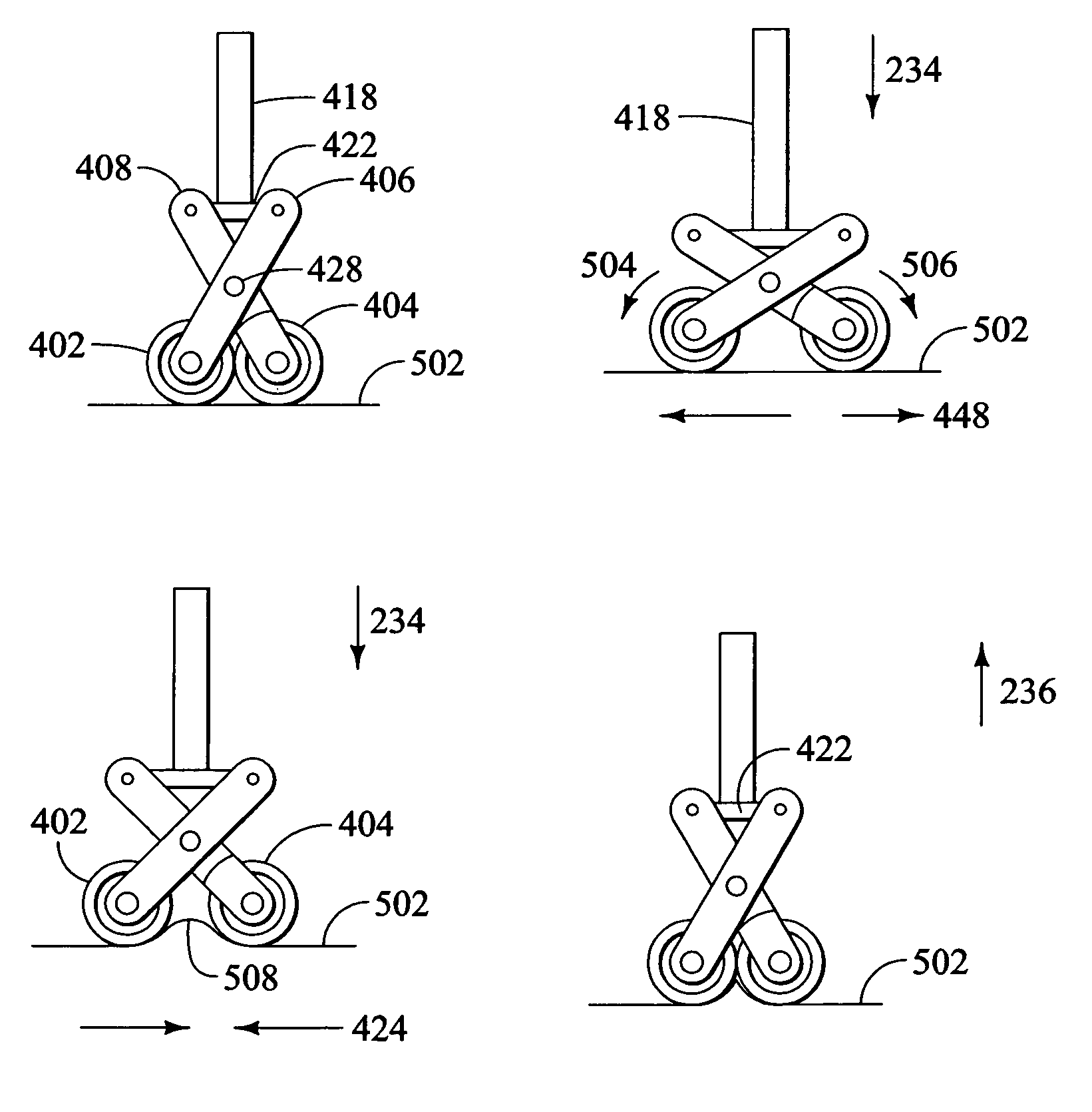
[0042]FIGS. 8A–8D is a sequence of operations showing how an interleaf sheet removal roller apparatus can be used to pick up an interleaf sheet;

[0043]FIG. 9 is a perspective view of a second embodiment of an exemplary interleaf sheet removal apparatus;

[0044]FIG. 10 is a second perspective view of a second embodiment of an exemplary interleaf sheet removal apparatus; and

[0045]FIGS. 11A–11D is a sequence of operations showing how a second embodiment of the interleaf sheet removal apparatus can be used to pick up an interleaf sheet.


PUM


Abstract

The present invention relates generally to systems and methods that remove an interleaf sheet interposed between plate sheets from a material stack used, for example, in a computer-to-plate imaging system and / or environment. Embodiments of the system and method can also remove plate sheets from an interleaf sheet, and transport the plate sheet for subsequent imaging.

Description

BACKGROUND OF THE INVENTION[0001]1. Field of the Invention[0002]The present invention relates generally to a system and method for removing and / or separating an interleaf sheet from a plate sheet and / or transporting a plate sheet, used in connection with, for example, Computer-to-Plate (CTP) imaging systems.[0003]2. Background Description[0004]Automating the printing process in CTP imaging systems involves the alternating process of extracting plate sheet material, and then interleaf sheet material, from a material stack. Images are exposed on the plate sheet material, and the interleaf sheet material is used to protect the imaging surface of plate sheets from each other.[0005]Interleaf sheets, though varying from manufacturer to manufacturer in material characteristics such as smoothness, porosity, and color, are generally paper-like with a thickness of about 0.003 inches. Plate sheet material typically varies in thickness from 0.005 inches to 0.012 inches.[0006]Extracting the inte...

Claims


Application Information

Patent Timeline
Patent Type & Authority Patents(United States)
IPC IPC(8): B41F1/30B65H3/02B65H3/06
CPCB65H3/02B65H2405/52B65H2405/57B65H2511/22B65H2701/18264B65H2220/01
Inventor YEE, CHANG J.BERRIGAN, JOHNDOUGHERTY, JAMES A.
Owner ECRM
Why Eureka
Try Eureka