Umbrella having solar powered illumination structure

a solar energy and umbrella technology, applied in the field of umbrellas, can solve the problems of blinding people, lighting devices form very strong localized bright areas, and light devices usually take a lot of power

Inactive Publication Date: 2006-02-21
CHANG TONY WEI SIN
View PDF11 Cites 94 Cited by
  • Summary
  • Abstract
  • Description
  • Claims
  • Application Information

AI Technical Summary

Benefits of technology

[0005]The present invention has been made to overcome the above mentioned shortcomings of the conventional lighted umbrella. An object of the invention is to provide an illumination structure for the lighted umbrella that can provide uniform and pleasant light. Another object is to provide an illumination structure that can last for a long time with solar power.
[0007]The hollow interior of each rib has an electrical wire that has one end connected to the solar power device and the other end connected with two light emitting diodes each being mounted on a respective transparent elongated rod through the opening space near the middle of the rib. Energy efficient devices such as light emitting diodes are used as the lighting devices to save energy provided by the solar power device. The transparent elongated rods guide the emitted light to increase the lighting area and form uniform and pleasant light.

Problems solved by technology

One is that the lighting devices usually take a lot of power which quickly drains out the charge in the batteries and hence the illumination only last a short period time.
The other is that the lighting devices form very strong localized bright areas that are blinding to people.

Method used


Image

  • Umbrella having solar powered illumination structure
  • Umbrella having solar powered illumination structure
  • Umbrella having solar powered illumination structure

Examples


Embodiment Construction

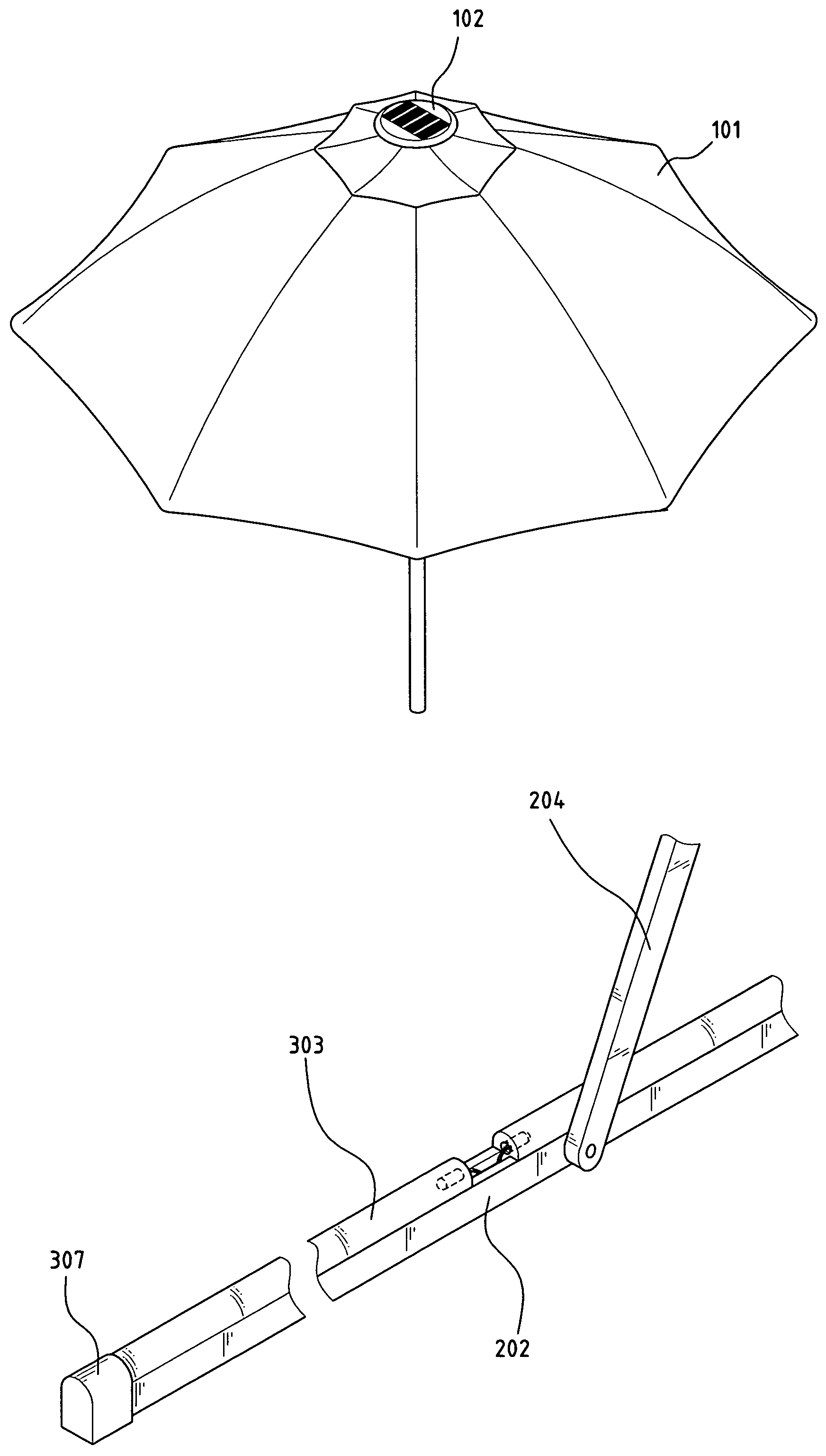
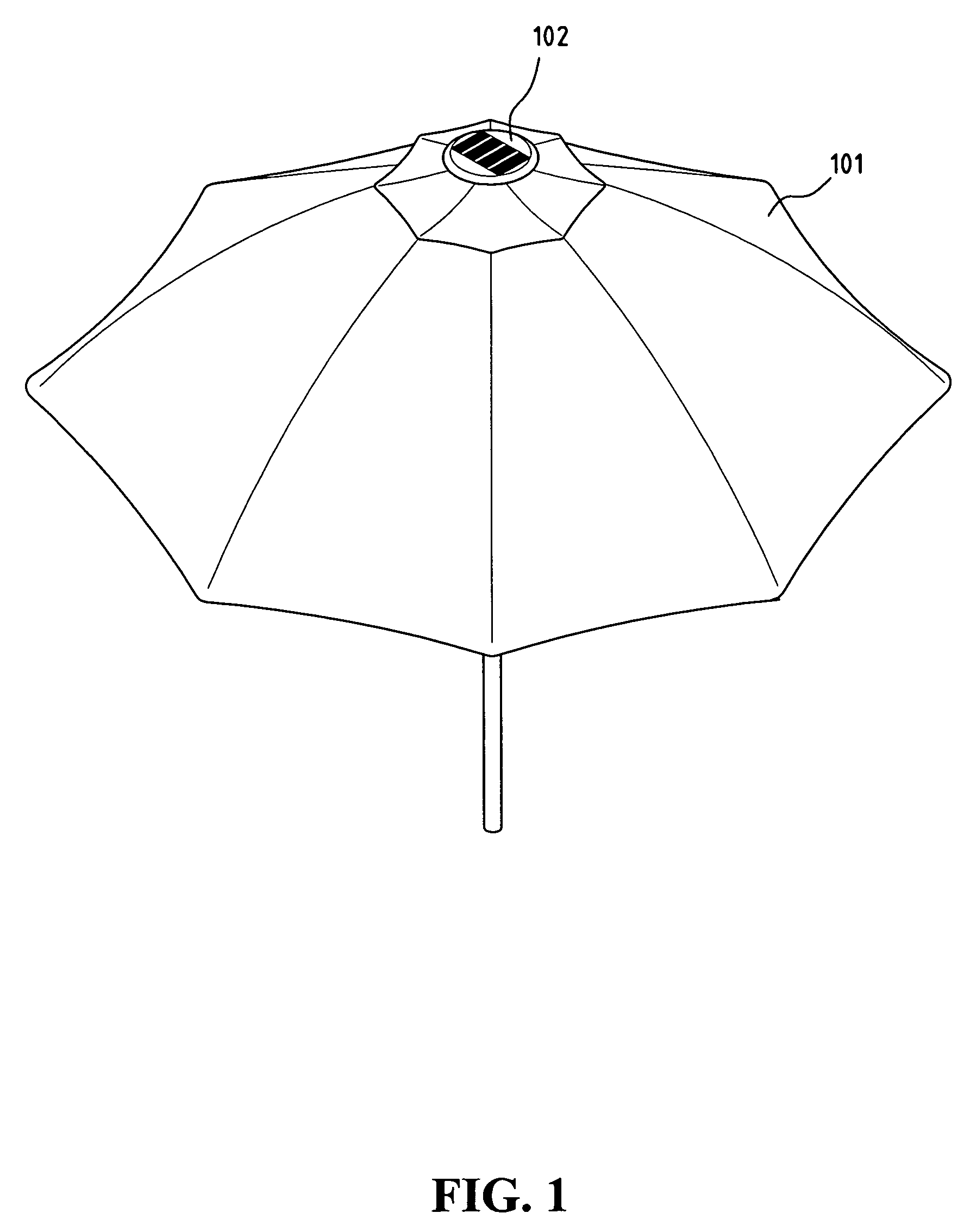
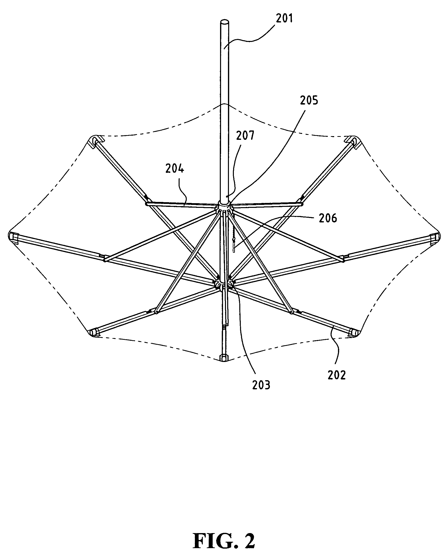
[0014]With reference to FIG. 1 of the drawings, a preferred embodiment of the umbrella having solar powered illumination arrangement of the present invention comprises a frame for supporting a fabric 101 thereon. A solar power device 102 is mounted to the top center of the frame through the fabric. FIG. 2 illustrates the interior view of the umbrella.

[0015]As shown in FIG. 2, the frame comprises a plurality of ribs 202 pivotally connected to a shaft 201 by means of a first connector 203. The ribs 202 extend radially from the first connector 203 that is affixed to the top end of the shaft 201. Each rib 202 has a supporting bar 204 with one end pivotally connected to the rib 202. The other end of the supporting bar 204 is pivotally connected to a second connector 205. The second connector 205 has a circular opening in the center for the shaft 201 to pass through and is movable along the shaft 201. The supporting bars 204 extend radially and outwardly from the second connector 205.

[001...


PUM


Abstract

A lighted umbrella comprises a solar power device mounted on the top end of the shaft of the umbrella. A plurality of ribs is pivotally connected to the shaft. Each rib has a hollow interior in which an electrical wire can be stored. A slot is formed on each rib to accommodate two transparent light guiding rods that are disposed on the slot to form an opening space near the middle of the rib. A plurality of lighting devices is affixed on the rods through the opening space. Energy efficient devices such as light emitting diodes are used as the lighting devices to save energy provided by the solar power device. A fabric supported by the ribs forms the shelter for the umbrella.

Description

FIELD OF THE INVENTION[0001]The present invention relates to a lighted umbrella, and more specifically to an umbrella having illumination structure powered by a solar power device.BACKGROUND OF THE INVENTION[0002]Umbrellas have served many purposes for human. Some small umbrellas are light and easily carried by people and some large umbrellas are heavier and usually installed in the patio or near the beach. They can be used to shelter from the rain or sunlight. Lighted umbrellas have also been designed to provide illumination for the convenience of night activities or serving as outdoor decoration.[0003]Lighted umbrellas powered by solar energy have become very popular in recent years because it does not require a power outlet or an extension cord to get the electrical power supply. In general, a solar power device having rechargeable batteries and solar cells are assembled on the top end of a shaft above the umbrella. Lighting devices mounted on the umbrella are powered by the sola...

Claims


Application Information

Patent Timeline
Patent Type & Authority Patents(United States)
IPC IPC(8): A45B3/02A45B3/04
CPCA45B3/04Y10S135/91A45B2200/1027A45B2200/1018
Inventor CHANG, TONY WEI-SIN
Owner CHANG TONY WEI SIN
Why Eureka
Try Eureka