Manually tightened drill chuck

a drill chuck and manufactured technology, applied in the field of manufactured tools, can solve the problems of large vibration and difficulty in assembly of the front sleeve, and achieve the effect of convenient and stable operation

Inactive Publication Date: 2006-02-21
ZHE JIANG SAN OU MASCH CO LTD
View PDF12 Cites 6 Cited by
  • Summary
  • Abstract
  • Description
  • Claims
  • Application Information

AI Technical Summary

Benefits of technology

[0009]To compare the manually tightened drill chuck according to the present invention with the prior art, the present invention has the following advantage of providing at least one key that is fixed in the key groove, acting as a torque transmission portion between the front sleeve and the nut. Thus, the drill chuck can run steadily when operating. Moreover, in order to fix the front sleeve on the inner sleeve, the protrusion of the front sleeve is snapped in a hole of the inner sleeve to axially position the front sleeve and the nut. Accordingly, the assemblage between the front sleeve and the rear sleeve is easier and stable after the assemblage there between. Thus, radial vibration thereof when the drill chuck is operating is eliminated.

Problems solved by technology

However, the disadvantages of the drill chuck lie in the key connections being adopted for torque transmission between the front sleeve and the nut sleeve.
Furthermore, since axial positioning of the sleeve is carried out by the engagement between the annular protrusions defined in the inner surface of the front end of the front sleeve and said recesses defined in the drill body, the front sleeve is not easy to assemble, and the rear end has no engaging space so that the front sleeve and its rear end would result in a large vibration when being operated.

Method used


Image

  • Manually tightened drill chuck
  • Manually tightened drill chuck
  • Manually tightened drill chuck

Examples


Embodiment Construction

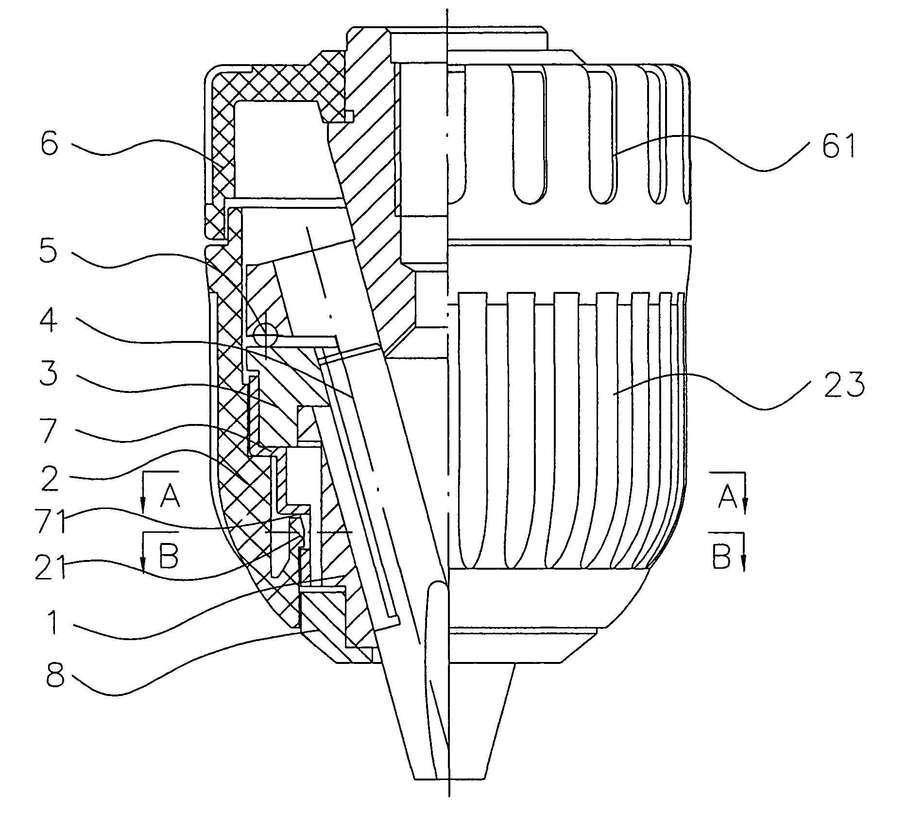
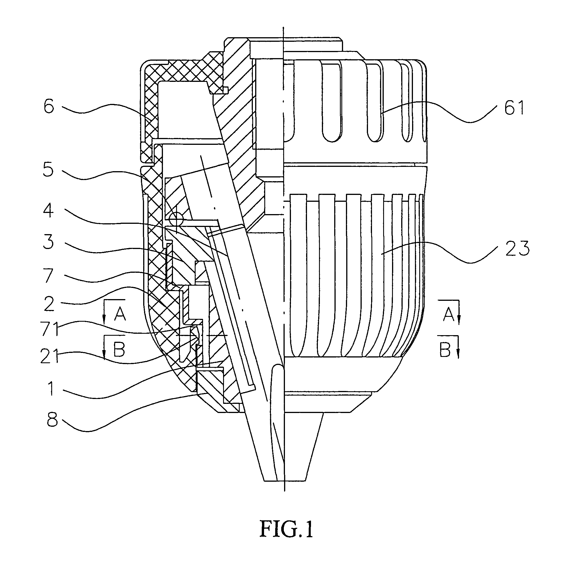
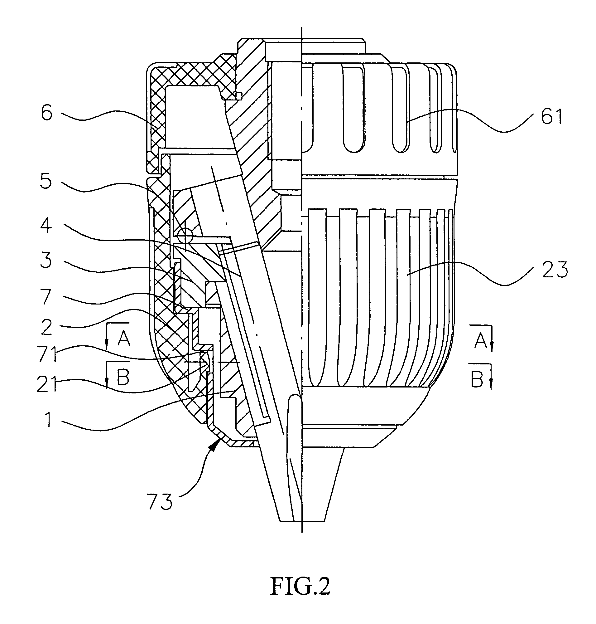
[0015]Referring to FIG. 1, a preferred embodiment of a manually tightened drill chuck according to the present invention is shown wherein a drill body 1 includes three inclined bores defined peripherally which are equally spaced. In each inclined bore, a jaw 4 is installed slidably. A nut 3 is provided in the middle of the drill body that is interconnected with each jaw 4 by cooperating threads. A front sleeve 2 is defined on the front end of the drill body, and a rear sleeve 6 is placed against the rear end thereof. Moreover, a plurality of bearings 5 are provided on the rear end of the nut 3, by which a relative rotational movement between the nut 3 and the drill body 1 may be achieved.

[0016]The nut 3 has a duplex-half structure with an external peripheral surface that is housed in an inner sleeve 7 by shrink fit. The inner sleeve 7 forms a body for rotation. Furthermore, a decorative sleeve 8 is mounted on the front end of the drill body 1.

[0017]As illustrated in FIG. 3, at least...


PUM


Abstract

A manually tightened drill chuck includes a drill body, a nut, a front sleeve and a rear sleeve. The front sleeve is provided on the front end of the drill body with the nut being provided in the middle. A decorative sleeve is mounted on the front end of the drill body with an external peripheral surface of the nut being housed in an inner sleeve by shrink fit. At least one key groove is located in the inner wall of the front sleeve. A key cooperates with the key groove. At least one locating member is provided in the lower end of the key that includes a hole. The front sleeve further defines at least one protrusion that corresponds to the position of the hole for snapping into the hole. Accordingly, the stability of the front sleeve and the rear sleeve without radial vibration is achieved.

Description

FIELD OF THE INVENTION[0001]The present invention relates to a drill chuck used in machine equipment. More particularly, to a manually tightened drill chuck which has a stable performance when it is mounted in a drilling machine.DESCRIPTION OF BACKGROUND ART[0002]In the prior art, a drill chuck generally comprises a chuck body, jaws, a nut, a front sleeve and a rear sleeve. For example, as set forth in Chinese Utility Model Patent No. 2322725 published on Jun. 9, 1999 a drill chuck is disclosed. Three jaws for the chuck are provided in three inclined bores distributed uniformly on the chuck body, respectively. Between the nut and the jaw, a thread connection is adopted. Moreover, a thrust bearing is provided in the rear end of the nut with a retaining ring being provided in the rear end of thrust bearing. The rear sleeve is mounted on the rear end of the drill body. The nut includes a duplex-half structure which is combined into an integral construction with a nut sleeve shrinking f...

Claims


Application Information

Patent Timeline
Patent Type & Authority Patents(United States)
IPC IPC(8): B23B31/169
CPCB23B31/1238Y10T279/17632Y10S279/902B23B2231/38
Inventor WENHUA, ZHOU
Owner ZHE JIANG SAN OU MASCH CO LTD
Why Eureka
Try Eureka