Pipe screw-connection

Inactive Publication Date: 2006-02-21
VOSS FLUID
View PDF27 Cites 86 Cited by
  • Summary
  • Abstract
  • Description
  • Claims
  • Application Information

AI Technical Summary

Benefits of technology

[0009]By virtue of the configuration according to the invention, the situation where the pipe rotates along in unison is very reliably avoided since the surface pressure in the inner stub cone is greater than in the region of the radial abutment surface between the annular pipe bead and supporting ring. When the screw-connection is tightened, the supporting ring, with the screw-connection part, is thus rotated relative to the connection stub and the pipeline, which is not rotated along in unison. In the region of the preferably conical abutment surface between the supporting ring and screw-connection coupling part, however, the fixed screw-connection causes the supporting ring to be pressed radially, which advantageously results in the pipe being reliably clamped in firmly, precisely in its non-deformed pipe region, which is spaced apart from the annular bead and is thus not work-hardened by the deforming operation. This avoids pipe ruptures under high dynamic loading in that, in the region of the radial abutment surface on the annular bead, by virtue of the 90° angle which is preferred according to the invention, a radial force component which counteracts the radial force on the other, conical abutment surf

Problems solved by technology

It is not possible in the case of this configuration to

Method used


Image

  • Pipe screw-connection
  • Pipe screw-connection
  • Pipe screw-connection

Examples


Embodiment Construction

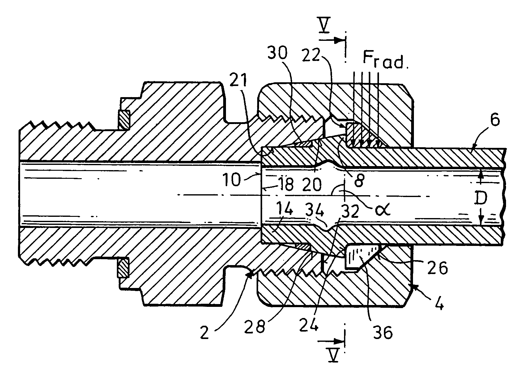
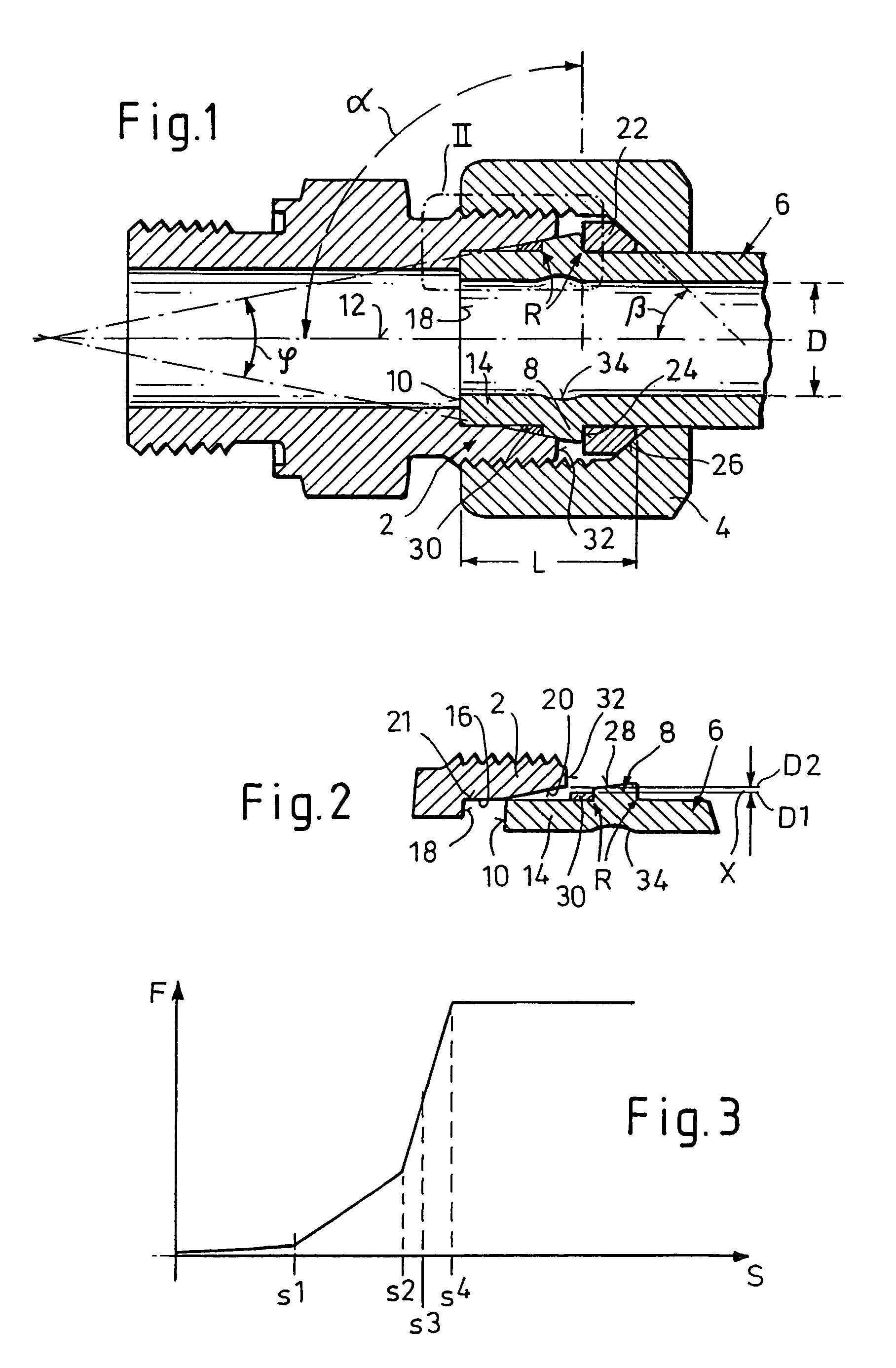
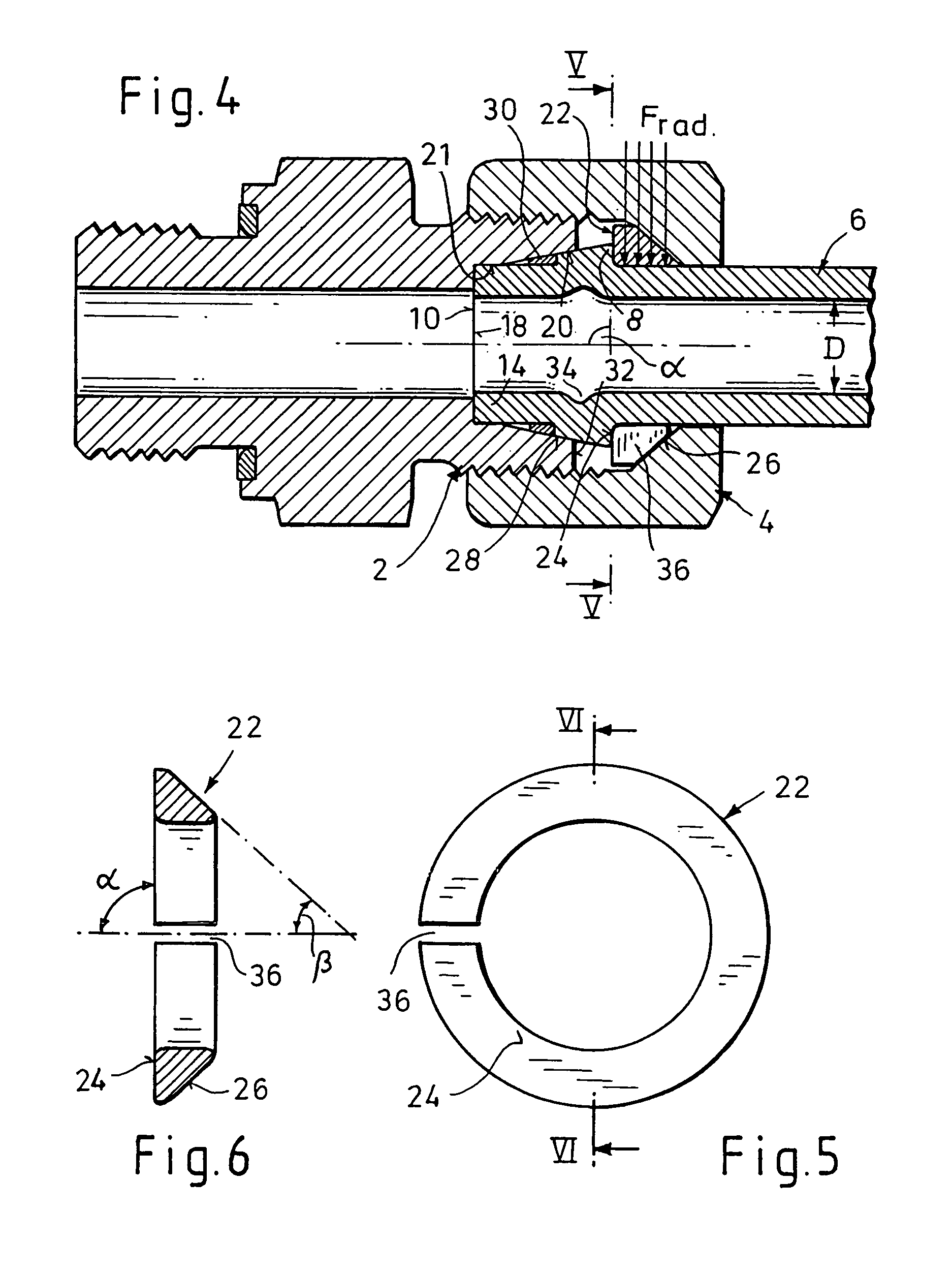
[0019]As can be gathered first of all from FIGS. 1 and 4 in each case, a pipe screw-connection according to the invention comprises a connection stub 2 and a screw-connection coupling part 4, which is usually designed as a coupling nut which can be screwed, by way of an internal thread, onto an external thread of the connection stub 2. And in particular metallic pipeline 6 which is to be connected has, at a connection end, a radially outwardly projecting annular bead 8, which is formed by being upset by plastic deformation. A hollow-cylindrical pipe end section 14, which is parallel to the screw-connection axis 12 (axis-parallel), is formed between the annular bead 8 and an end surface 10 of the connection end of the pipeline 6. The connection stub 2 has an accommodating opening 16 (FIG. 2) with a radial step surface 18 for axially supporting the pipeline 6 by abutment of the end surface 10. In addition, an inner cone 20 is formed within the accommodating opening 16, said inner cone...


PUM


Abstract

A pipe screw-connection for connecting a pipeline having a connection end with a deformed annular bead, including a connection stub and a screw-connection coupling part, which can be screw-connected to the connection stub in order to retain the pipeline in a sealed manner is provided. The connection stub has an accommodating opening with a radial step surface for axially supporting an end surface of the pipeline and with an inner cone which widens outward away from the step surface. The pipeline can be clamped in, by way of the annular bead, with a form fit between the connection stub and a supporting ring, which is seated on the pipeline between the annular bead and the screw-connection part. The supporting ring, with the annular bead, forms an abutment surface which is at an angle (α) considerably greater than 45° to the screw-connection axis.

Description

FIELD OF THE INVENTION[0001]The present invention relates to a pipe screw-connection for connecting a pipeline.BACKGROUND OF THE INVENTION[0002]The pipeline is of a type having a connection end with a deformed annular bead, comprising a connection stub and a screw-connection coupling part, which can be screw-connected to the connection stub in order to retain the pipeline in a sealed manner. The connection stub has an accommodating opening with a radial step surface for axially supporting an end surface of the pipeline and with an inner cone which widens outward away from the step surface. The pipeline may be clamped-in, by way of the annular bead, with a form fit between the connection stub and a supporting ring, which is seated on the pipeline between the annular bead and the screw-connection part.[0003]Numerous configurations of pipe screw-connections for connecting prefabricated pipelines each having an annular bead formed by an upsetting operation are known. Examples include th...

Claims


Application Information

Patent Timeline
IPC IPC(8): F16L19/00F16L19/02F16L19/028F16L19/03
CPCF16L19/0218F16L19/0286F16L19/0283
Inventor BERGHAUS, GERD
Owner VOSS FLUID
Why Eureka
Try Eureka