Uniform pupil illumination for optical inspection systems

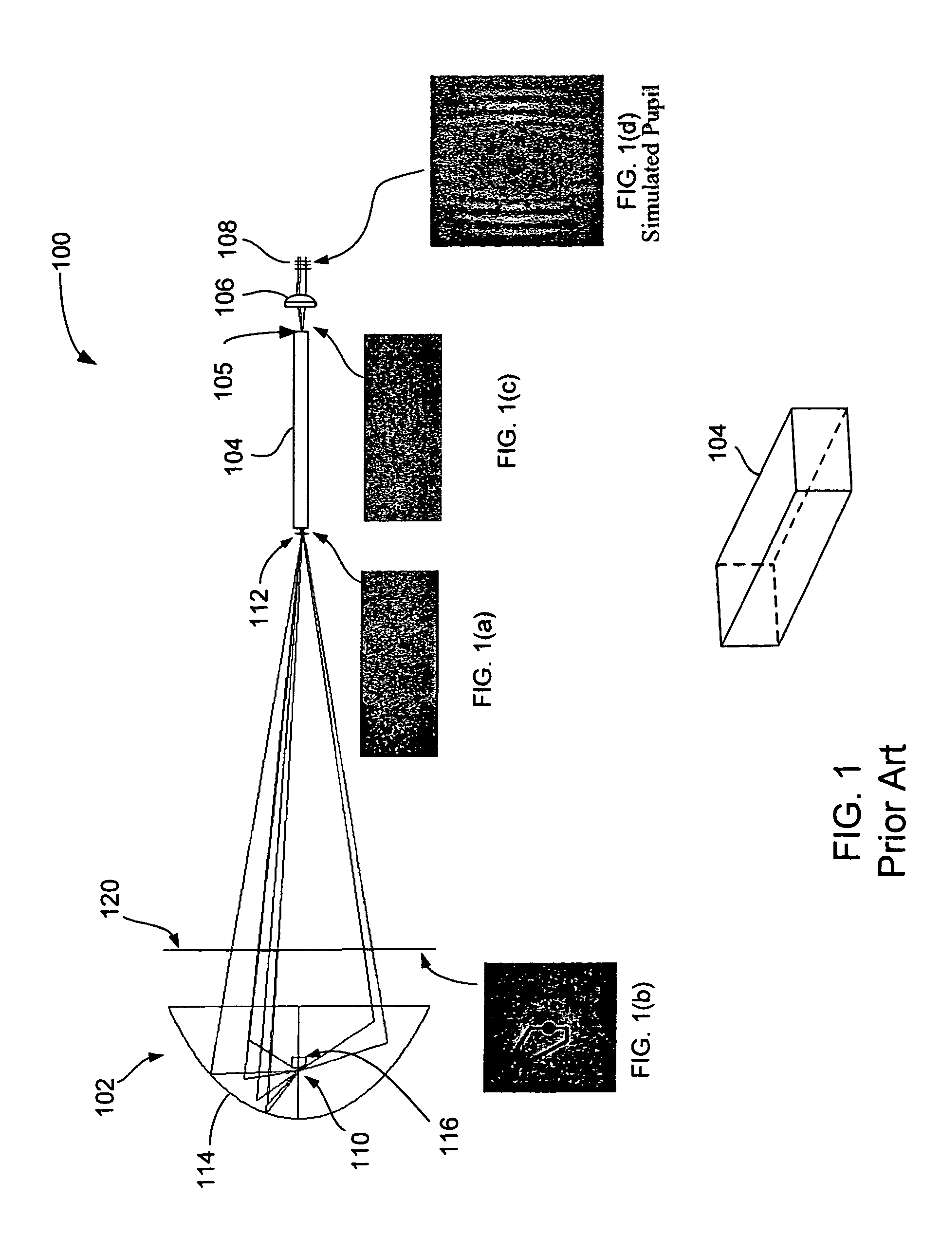
a technology of optical inspection and illumination, applied in the direction of fixed installations, lighting and heating devices, instruments, etc., can solve the problems of reducing the effectiveness of the inspection system, the illumination aperture which uses light from the edge of the pupil to be less effective, and the light emanating from the illumination source 102 to be non-uniform in nature, so as to increase the inspection resolution and sensitivity

Active Publication Date: 2006-02-21
KLA TENCOR TECH CORP
View PDF1 Cites 36 Cited by
  • Summary
  • Abstract
  • Description
  • Claims
  • Application Information

AI Technical Summary

Benefits of technology

[0016]The present invention is directed to an illuminator for uniformly illuminating an entrance pupil and a field stop of an inspection system in order to increase inspection resolution and sensitivity, and make tool-to-tool matching achievable. The illuminator incorporates at least two lightpipes for spatially and angularly distributing light rays from the light source uniformly across the entrance pupil.

Problems solved by technology

Any deviation from the uniform nature of the spatial and angular illumination will reduce the effectiveness of the inspection system through either less sensitivity or inability to match multiple inspection systems on the same specimen.
Unfortunately, various factors cause light emanating from illumination source 102 to be non-uniform in nature when the light reaches entrance pupil 108.
If there is not much light near the edge of the pupil, then illumination apertures which use light from the edge of the pupil will be less effective.
Generally, non-uniform light causes a sample to be unevenly illuminated and thereby results in inspection signals having non-uniform sensitivity and will not match between inspection systems.
Unfortunately, it can be seen in FIG. 1(d) that the light at entrance pupil 108 is highly spatially non-uniform and this will result in non-uniform illumination angles at the specimen.
The distribution of light at the pupil can adversely affect the system's resolution and its sensitivity to defect capture.
In addition, the matching of one system to another system is dependent upon the same non-uniform illumination being achieved in each system's entrance pupil.
Since this non-uniformity is a result of many factors already mentioned, it is difficult to achieve this requirement.
These condensers also suffer from angular non-uniformities, which result in entrance pupil non-uniformities due to lens aberrations, anti-reflection differences as a function of incidence angle and the obscurations from cathode and anode and their connection wiring.
However, it is difficult to achieve a uniform pupil with a diffuser as it tends to produce a Guassian distribution of light leaving it.
Also, diffusers are generally not very light efficient, need to be rotated at high velocity (e.g., 10,000 to 20,000 rpm), and can be expensive.
In all cases, these suffer from the inability to remove the basic Gaussian distribution of the laser at either the entrance pupil or field stop.

Method used


Image

  • Uniform pupil illumination for optical inspection systems
  • Uniform pupil illumination for optical inspection systems
  • Uniform pupil illumination for optical inspection systems

Examples


Embodiment Construction

[0025]The present invention will now be described in detail with reference to a few preferred embodiments as illustrated in the accompanying drawings. In the following description, numerous specific details are set forth in order to provide a thorough understanding of the present invention. It will be apparent, however, to one skilled in the art, that the present invention may be practiced without some or all of these specific details. In other instances, well known operations have not been described in detail so not to unnecessarily obscure the present invention.

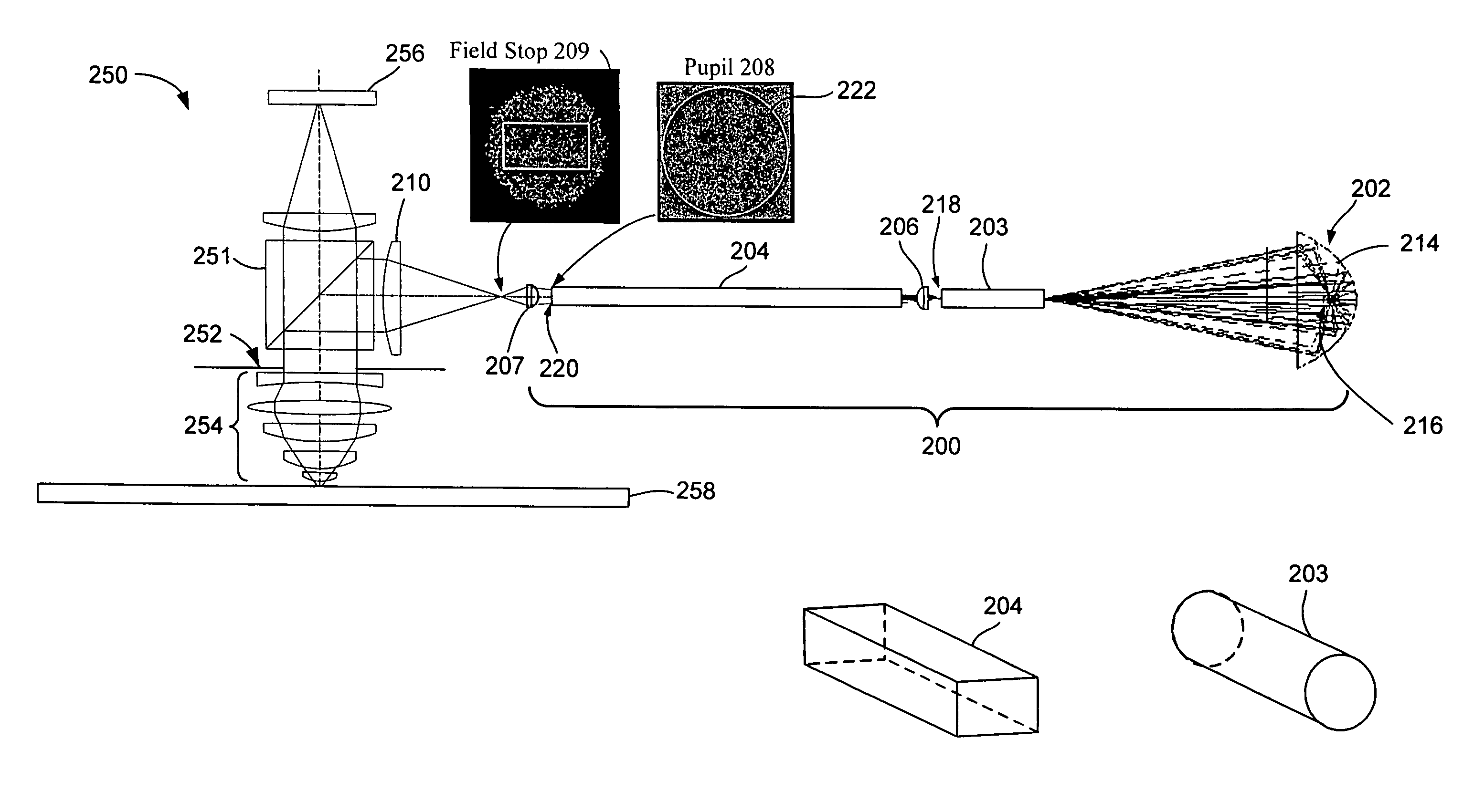
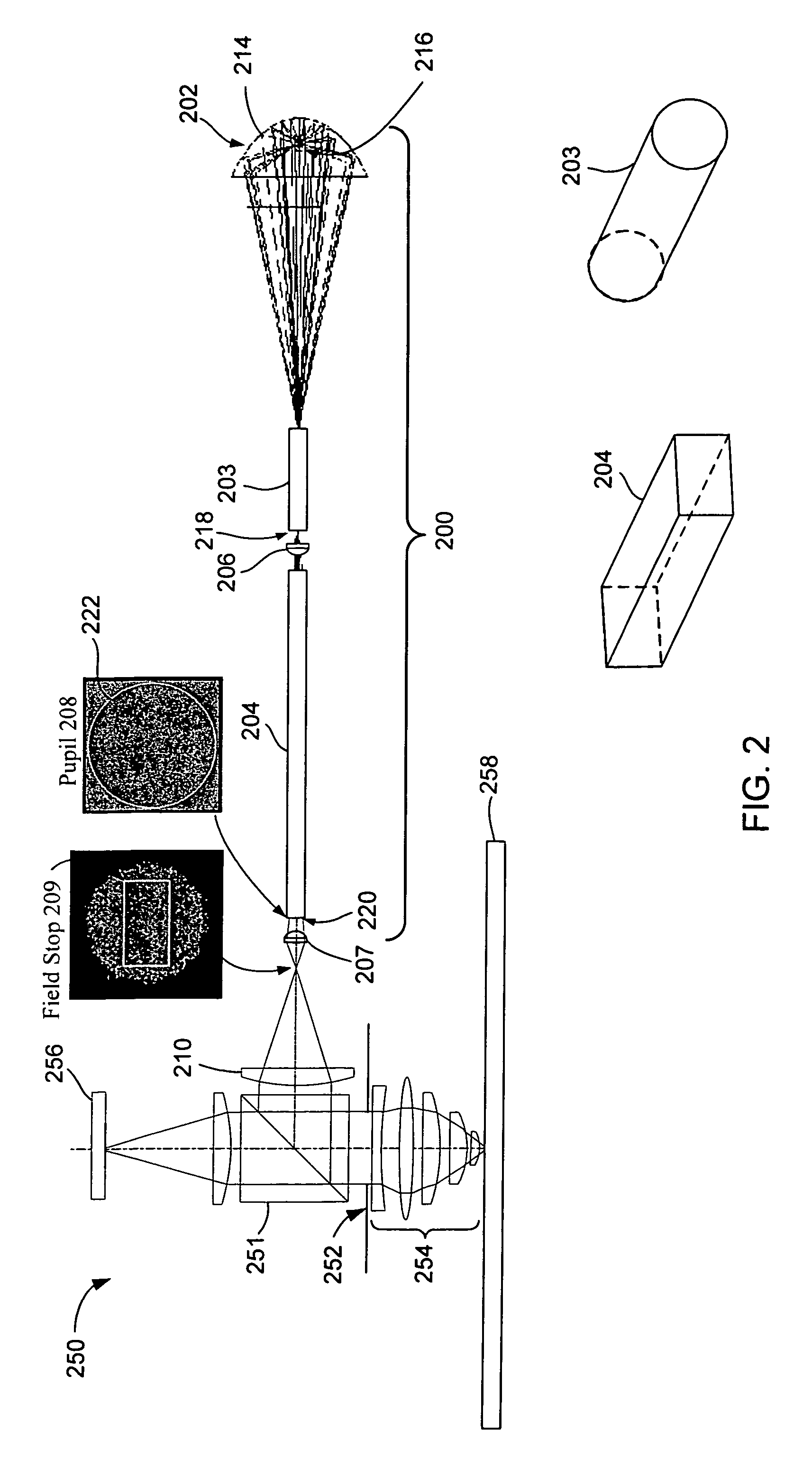
[0026]The present invention pertains to an illuminator for uniformly illuminating both an entrance pupil and a field stop of an inspection system in order to increase inspection resolution and sensitivity and to provide tool-to-tool matching. The illuminator incorporates at least two lightpipes for spatially distributing light rays from the illuminator uniformly across the entrance pupil and spatially distributing light ray...


PUM


Abstract

An illuminator for uniformly illuminating an entrance pupil of an inspection system in order to increase inspection resolution and sensitivity and improve system-to-system matching is described. The illuminator incorporates at least two lightpipes for spatially and angularly distributing light rays from the illuminator uniformly across the entrance pupil. The illuminator also results in spatial and angular uniformity at the field stop plane. In one embodiment, one lightpipe has a circular shape and a second lightpipe has a rectangular shape.

Description

[0001]This application claims priority of U.S. provisional patent application No. 60 / 540,851, filed on Jan. 30, 2004, which is hereby incorporated by reference.FIELD OF THE INVENTION[0002]The present invention relates generally to optical inspection and review systems, and more specifically to illumination techniques for optical inspection and review systems.BACKGROUND OF THE INVENTION[0003]Inspection and review systems play an integral role in the semiconductor manufacturing industry. The primary role of inspection systems is to optimize the quality of manufacturing systems, which will minimize the number of semiconductor devices produced with defects thereby increasing yield. The performance requirements of inspection systems continue to increase as the size of semiconductor devices continues to decrease. For instance, the resolution and sensitivity requirements of inspection systems are becoming more stringent as they need to detect smaller sized defects in accordance with the sm...

Claims


Application Information

Patent Timeline
Patent Type & Authority Patents(United States)
IPC IPC(8): G02B6/00
CPCG02B27/0994G02B6/4298
Inventor LANGE, STEVEN R.
Owner KLA TENCOR TECH CORP
Why Eureka
Try Eureka