Method of retrofitting a decanting centrifuge

a centrifuge and retrofitting technology, applied in the direction of centrifuges, rotary centrifuges, etc., can solve the problems of major and costly parts of the centrifuge that have substantial useful life remaining, wear out, and eventually need to be replaced

Inactive Publication Date: 2006-02-21
HUTCHISON HAYES PROCESS MANAGEMENT
View PDF12 Cites 43 Cited by
  • Summary
  • Abstract
  • Description
  • Claims
  • Application Information

AI Technical Summary

Benefits of technology

[0009]The present invention addresses this need in the art by providing a method of retrofitting a known centrifuge. The known centrifuge includes a bowl formed of tandem sections and this feature is used to advantage in the method of the present invention to alter the configuration of the beach. This step in the method requires modification to the bowl and screw conveyor, and this modification must be accomplished within the constraint of a longitudinal distance between pedestals on which the existing machine is mounted.

Problems solved by technology

No matter how well a piece of machinery is built, eventually it will wear out.
Within a limited number of hours of high speed operation, a centrifuge likewise will require maintenance and eventually will have to be replaced because of worn parts.
However, even with much of a centrifuge at the end of its useful life, major and costly portions of the centrifuge have substantial useful life remaining.
This means that a large, expensive piece of machinery is often scrapped because only part of the machine is worn out.
Such full scale machinery replacement is often a major expenditure and is not undertaken lightly.

Method used


Image

  • Method of retrofitting a decanting centrifuge
  • Method of retrofitting a decanting centrifuge
  • Method of retrofitting a decanting centrifuge

Examples


Embodiment Construction

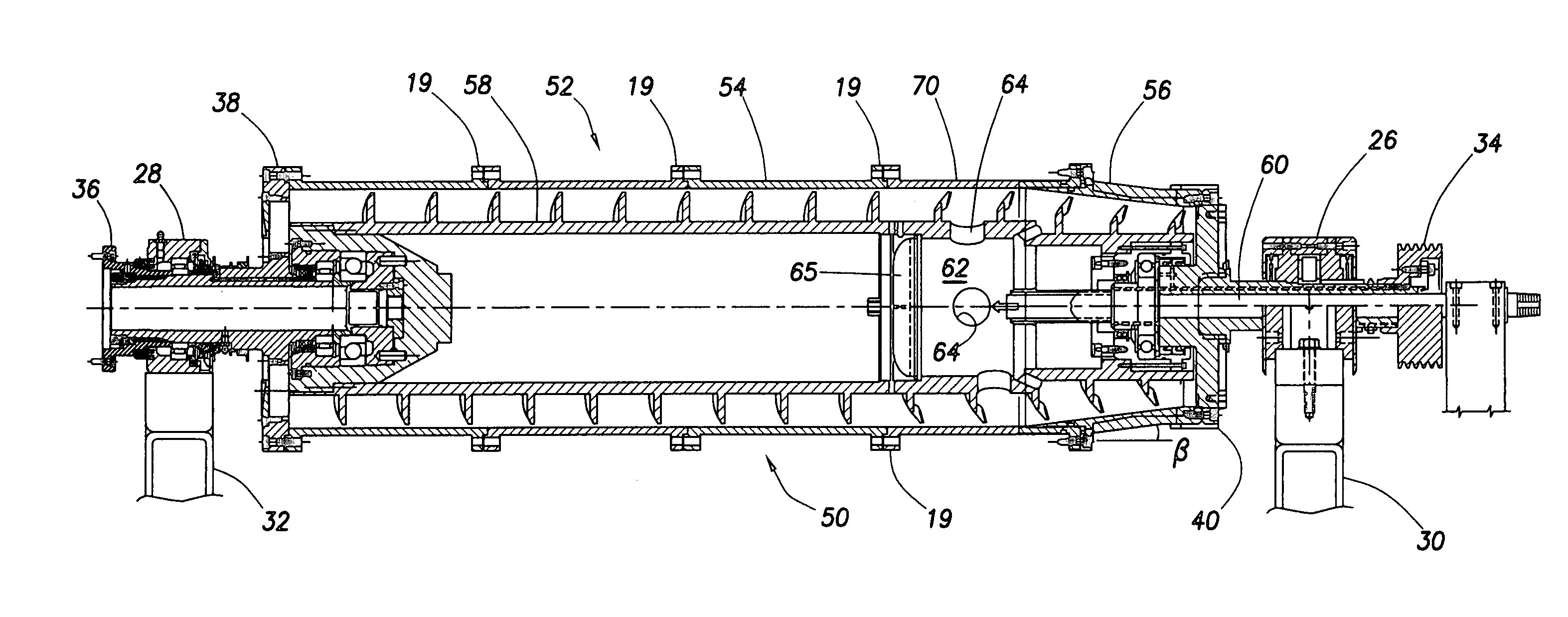
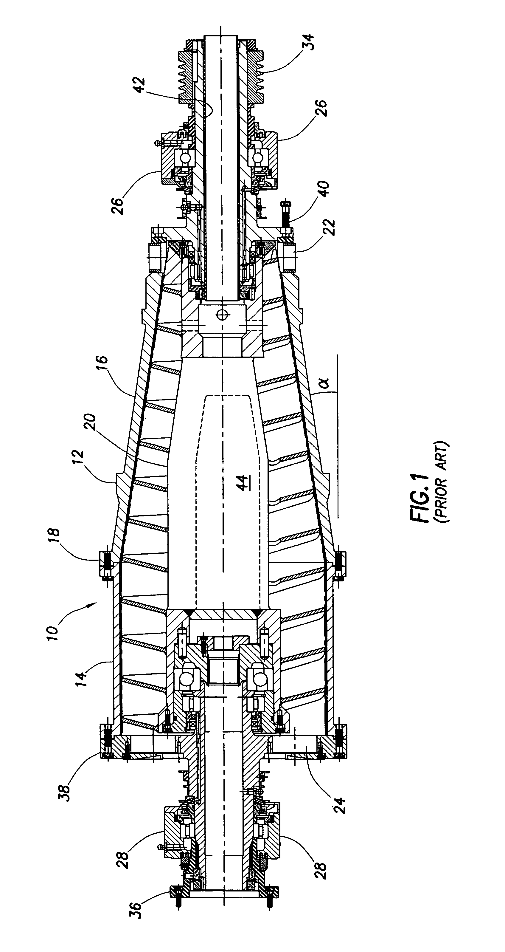
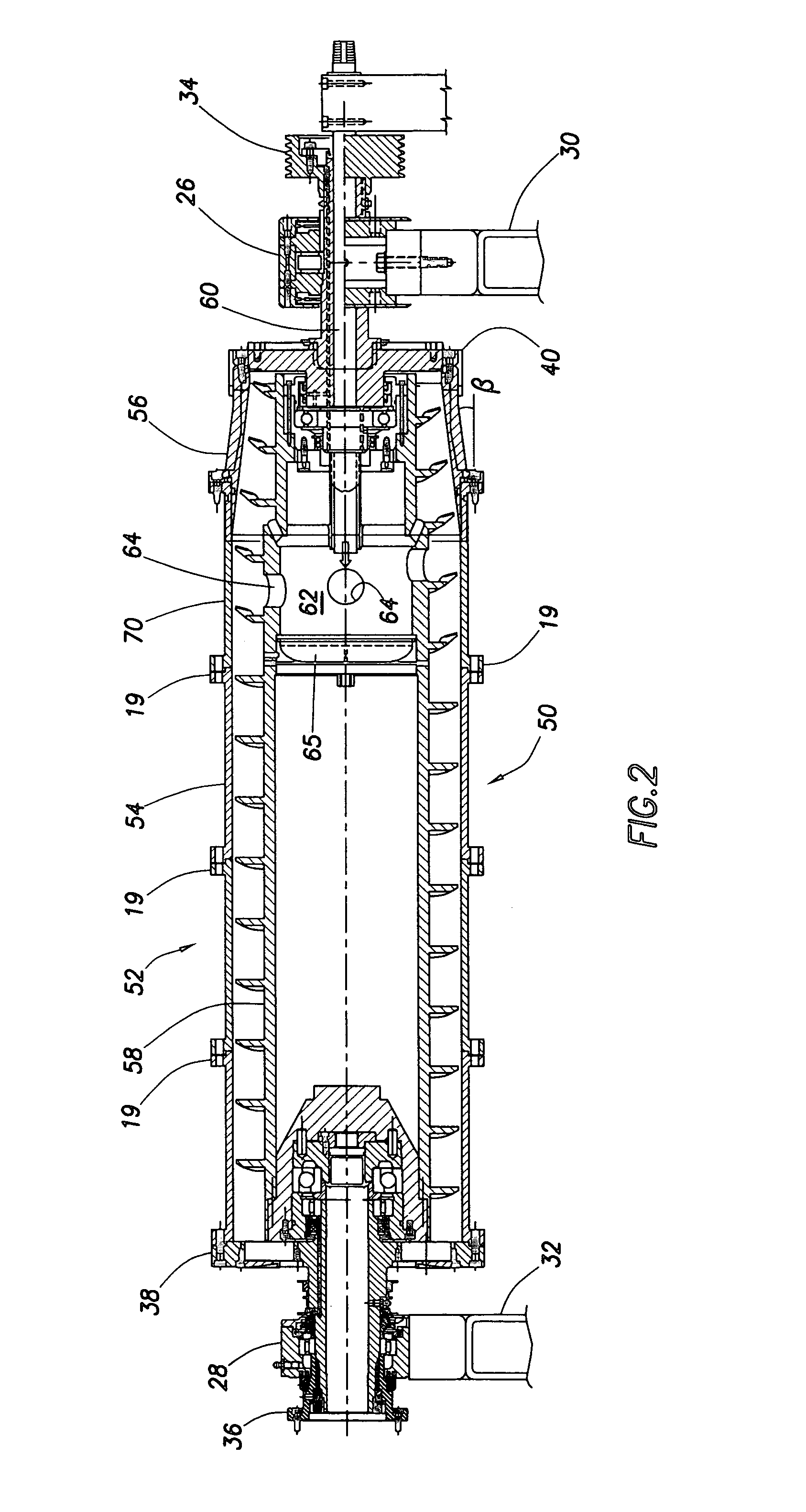
[0015]FIG. 1 depicts a decanting centrifuge 10 which is to be retrofitted by the method of the present invention. The centrifuge 10 comprises an outer body 12 which includes a bowl section 14 and a conical section 16, joined together at a flanged joint 18. The bowl section defines a slope angle of α. In practice, a plurality of bowl sections 14 are provided, thereby enabling a bowl section of a selectable length.

[0016]Enclosed within the outer body 12 is a screw conveyor 20, coaxial with the outer body for rotation therein. The outer radial profile of the screw conveyor 20 is in close proximity with the inner surface of the outer body, both the bowl section and the conical section, to convey solids toward the right as viewed in FIG. 1, and out through a solids discharge 22. Liquids are discharged through a liquids discharge port 24.

[0017]The centrifuge is supported on the solids end by a solids end pillow block 26 and on the liquids end by a liquids end pillow block 28. The pillow b...


PUM


Abstract

A method of retrofitting a centrifuge is provided. The method includes disassembling a known centrifuge and replacing a bowl section of the centrifuge outer body with a longer bowl section. The method further comprises replacing the conical beach section with a shorter beach section, i.e. a beach section having a greater slope. The screw conveyor is replaced with another screw conveyor having outlet nozzles adapted to impart rotational movement to the inlet feed. The retrofitted centrifuge provides enhanced performance through an additional length of cylindrical section, thereby making the clarification length longer, and improving the effectiveness of the centrifuge in removing solids from the inlet feed. The retrofitted centrifuge preferably remains mounted to the same pedestal as the centrifuge prior to retrofit.

Description

[0001]This application claims the benefit of U.S. Provisional Patent Application Ser. No. 60 / 438,650 filed Jan. 8, 2003.FIELD OF THE INVENTION[0002]The present invention relates generally to the field of decanting centrifugal separators, and, more particularly, to a method of retrofitting a decanting centrifuge to extend the useful life of such a centrifuge while substantially improving its performance.BACKGROUND OF THE INVENTION[0003]A decanting centrifuge is commonly used for separating solid matter from a solids-laden liquid. For example, drilling mud with solids entrained therein must be effectively cleaned so that the drilling mud can be recycled. For another example, many manufacturing and food processing systems use vast quantities of water. In such systems, the water picks up solid waste matter which must be removed from the water before it can be discharged, whether it is into the environment or into storage. Decanter centrifuges have proved to be effective and efficient in...

Claims


Application Information

Patent Timeline
Patent Type & Authority Patents(United States)
IPC IPC(8): B04B1/20B04B11/00
CPCB04B1/20
Inventor HENSLEY, GARY L.HILPERT, LEE
Owner HUTCHISON HAYES PROCESS MANAGEMENT
Why Eureka
Try Eureka