
Operational element comprising magnetic shape memory alloy and a method for manufacturing it

a technology of magnetic shape memory alloy and operation element, which is applied in the field of operation element, can solve the problems of difficult and expensive process of assembling all these parts in a small scale, slow actuation velocity and acceleration, and sometimes not being able to achieve any effect, and achieve the effect of simplifying many devices

Pending Publication Date: 2021-10-21
TIKOMAT OY
View PDF0 Cites 0 Cited by
  • Summary
  • Abstract
  • Description
  • Claims
  • Application Information

AI Technical Summary

Benefits of technology

The patent describes a method for creating magnetic elements with specific configurations using a mechanical force or a magnetic field. These elements can then be used to create operating elements that have certain regions that will not be active. The method allows for the creation of active regions with twin variants that can change their configuration when a magnetic field is applied, while maintaining the overall volume fraction of twin variants within the active region. This allows for the creation of elements with specific magnetic configurations that can be controlled using a magnetic field. The method can be used to create thin films using various techniques such as lithography or laser cutting.

Problems solved by technology

MSM devices exhibit significant commercial potential in micro- and nano-scale devices due to a lack of suitable active technologies that can produce large strokes in micro and nano devices.
Small-scale MSM devices benefit best from the high actuating velocity and acceleration because the actuation velocity and acceleration are mostly limited by the inertia of the moving part of the MSM element.
Larger MSM devices are slower than small devices.
Assembling all these parts in a small scale is a difficult and expensive process, and sometimes not possible at all.
It is also very difficult to prepare a proper twin structure in tiny MSM samples and assemble those elements precisely into micro devices.

Method used


Image

  • Operational element comprising magnetic shape memory alloy and a method for manufacturing it
  • Operational element comprising magnetic shape memory alloy and a method for manufacturing it
  • Operational element comprising magnetic shape memory alloy and a method for manufacturing it

Examples


example 1

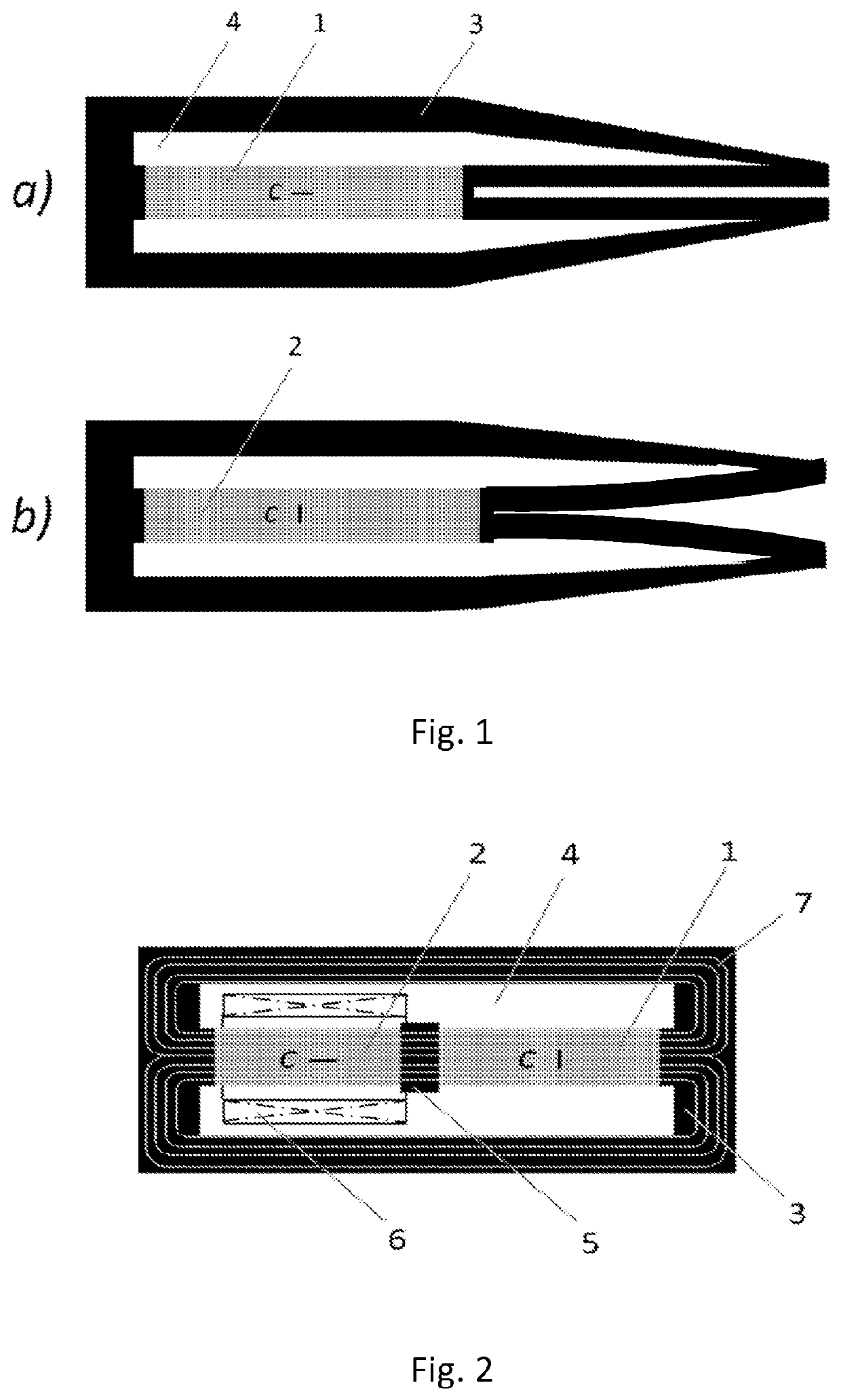
[0033]A gripper was made from a Ni—Mn—Ga foil of 0.1 mm in thickness. Foil was compressed in single variant state and thereafter surfaces of the foil were deformed by shot peening for blocking the twin boundary motion. Gripper similar to that schematically shown in FIG. 1 was cut from the sheet using a laser beam. Length of gripper was 5 mm and width of 2.6 mm After cutting, inactive regions were covered with a lacquer layer and the gripper was electropolished. Lacquer layer prevents electropolishing of the inactive regions. Active region was electropolished in such a way that part of the deformation by shot peening remains and stabilizes the dense twin structure that forms by the applied magnetic field. The operation of the gripper was demonstrated by applying a magnetic field on the active region.

example 2

[0034]FIG. 8a shows a principle of a pump that is made from a sheet Ni—Mn—Ga sheet. The active region (9) acts as a pumping element. Ratio of twin variants 1 and 2 is 70% and 30%. External local magnetic field (6) creates a shrinkage in the active region. The shrinkage (10) travels along the active region (9) when a local substantially vertically aligned magnetic flux (6) moves from left to right transferring fluid from the inlet to outlet. The inactive area (3) of the apparatus acts as frame of the pump.

[0035]FIG. 8b shows another embodiment of a pump that was made from a Ni—Mn—Ga sheet. A dense twin structure with equal proportions of the twin variants 1 and 2 was made in the sheet prior to laser cutting of the sheet into the form of the pump that is shown in the figure. Thereafter, twin boundary motion was blocked by laser treating the surfaces of the inactive region (3). Active region (9) was slightly shot peened for keeping the dense twin structure. FIG. 8b shows the operationa...

example 3

[0036]If an element is constrained between an object, e.g., a plate or a bar, with a substantially planar surface and another substantially planar surface as well as having both ends constrained, the object can move in the axial direction of the element when at least one local magnetic field source is applied to the element. This is based on the fact that the dimensions of the element change locally. For instance, in the 10 M martensite of Ni—Mn—Ga alloys, the element elongates in the axial direction in those locations where it shrinks in the perpendicular direction. When the shrinkage travels along the element, the planar surface placed on the element moves along the element. This is a principle of a linear motor whose operation was demonstrated.


PUM

PropertyMeasurementUnit
volume fractionaaaaaaaaaa
actuating velocityaaaaaaaaaa

Abstract

This invention relates to an operational element and a method for manufacturing the operational element that comprises magnetic shape memory alloy. in the method at least a part of the magnetic shape memory alloy is arranged as an active region that is responsive to a magnetic field and at least one other part of the magnetic shape memory alloy is arranged as an inactive region that is unresponsive to a magnetic field.

Description

CROSS-REFERENCE TO RELATED APPLICATIONS[0001]This is a National Stage Application under 35 U.S.C. § 371 of PCT / FI2019 / 050613, filed on Aug. 28, 2019, which claims priority to Finnish Patent Application having serial number 20180095, filed on Aug. 28, 2018, which is incorporated by reference herein.BACKGROUND OF THE INVENTIONField of the Invention[0002]The invention relates to an operational element as defined in the preamble of claim 1 and a method for manufacturing the operational element as defined in the preamble of claim 16.[0003]The operational element according to the invention comprises magnetic shape memory alloy material and is intended as an operational or functional element for various devices and apparatuses. In the operational element certain regions, defined here as active regions, can be actuated by means of the Magnetic Shape Memory (MSM) effect, and other regions are made inactive using special manufacturing methods so that those inactive regions do not strain in th...

Claims


Application Information

Patent Timeline
Patent Type & Authority Applications(United States)
IPC IPC(8): H01L41/47H01L41/12H01L41/20B01L3/00C22C19/00C22F1/10F03G7/06H10N35/01H10N35/00H10N35/85
CPCH01L41/47H01L41/12H01L41/20B01L3/50273F16K99/0046C22F1/10F03G7/06147B01L2200/10C22C2202/02C22C19/005F03G7/065C22C19/03F04B43/043H10N35/00H10N35/01H01F1/0308H01F1/0306F05B2280/5006F03G7/0614F04B43/04H10N35/85
Inventor ULLAKKO, KARI
Owner TIKOMAT OY
Learn More