Anterior cervical plating system

a technology of anterior cervical and plate, which is applied in the field of anterior cervical plate, can solve the problems of compromising the load bearing and support capacity of the spine, affecting the stability of the spine, and affecting the stability of the spine, and achieves the effect of low spine profil

Inactive Publication Date: 2006-02-21
SDGI HLDG
View PDF74 Cites 164 Cited by
  • Summary
  • Abstract
  • Description
  • Claims
  • Application Information

AI Technical Summary

Benefits of technology

[0021]One benefit achieved by the present invention is that the fixation plate and locking assembly maintain a low profile within the spine. A further benefit is accomplished by the ability to select either a fixed angle or a variable angle screw at any instrumented level and within a single fixation plate.

Problems solved by technology

As with any bony structure, the spine is subject to various pathologies that compromise its load bearing and support capabilities.
In the Spinal Instrumentation text, as well as in other documentation in this field, it is stressed that complications associated with any spinal procedure, and most particularly within the tight confines of cervical procedures, the complications can be very devastating, such as injury to the brain stem, spinal cord or vertebral arteries.
At present, no plating system is known that allows for the placement of bone screws in either a semi-rigid or a rigid construct with a single plate.
While some plates will provide for either one of these screw fixations, no plating system allows the surgeon to use a single plate and to select which of the two types of fixation is desired for the particular spinal pathology and anatomy.

Method used


Image

  • Anterior cervical plating system
  • Anterior cervical plating system
  • Anterior cervical plating system

Examples


Embodiment Construction

[0046]For the purposes of promoting an understanding of the principles of the invention, reference will now be made to the embodiment illustrated in the drawings and specific language will be used to describe the same. It will nevertheless be understood that no limitation of the scope of the invention is thereby intended. Any alterations and further modifications in the described device, and any further applications of the principles of the invention as described herein are contemplated as would normally occur to one skilled in the art to which the invention relates.

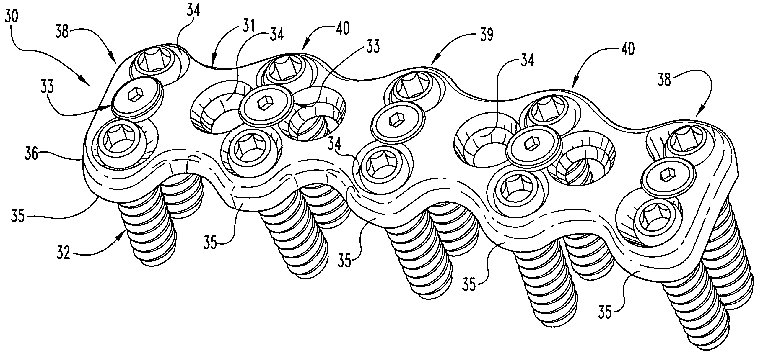
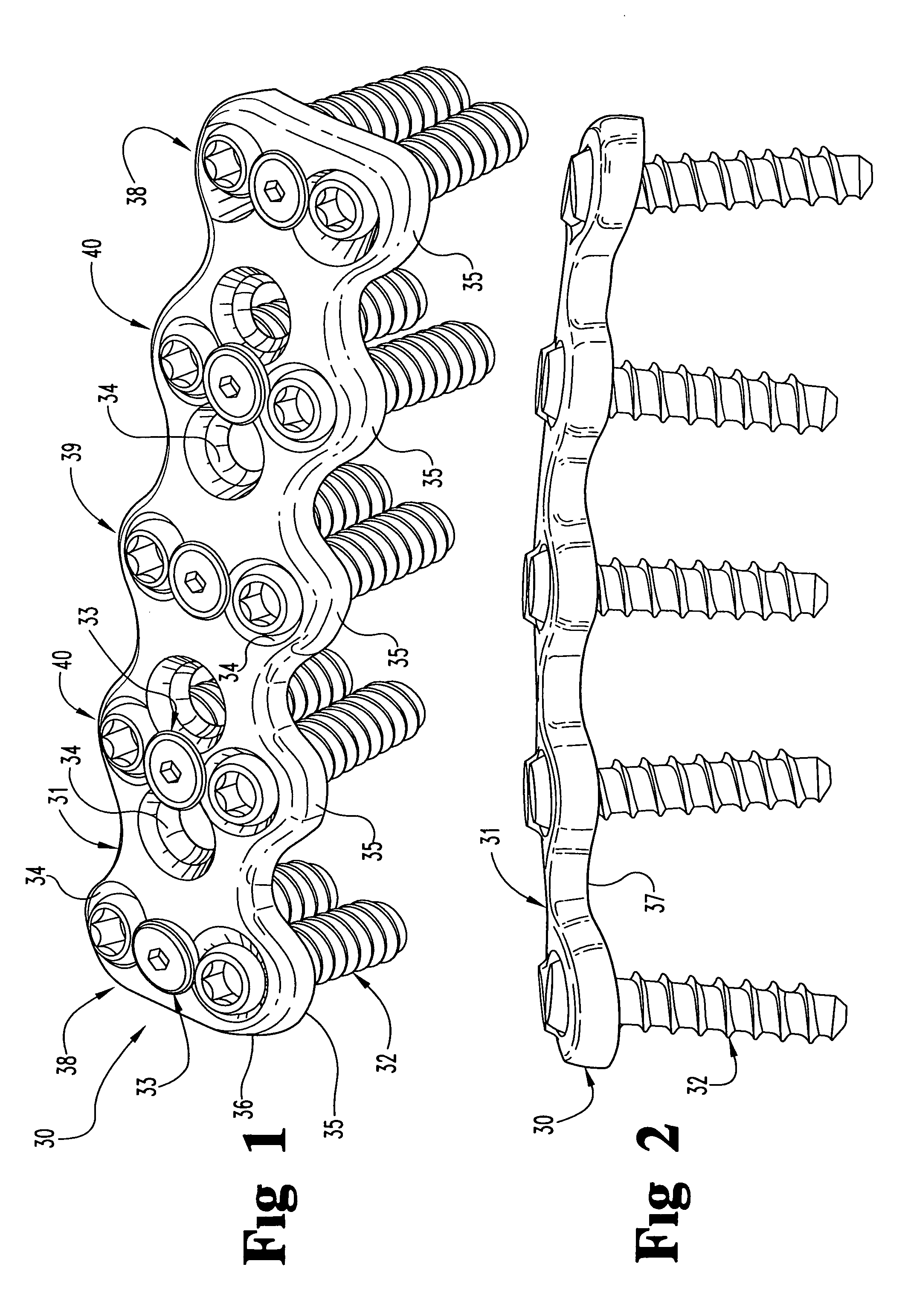
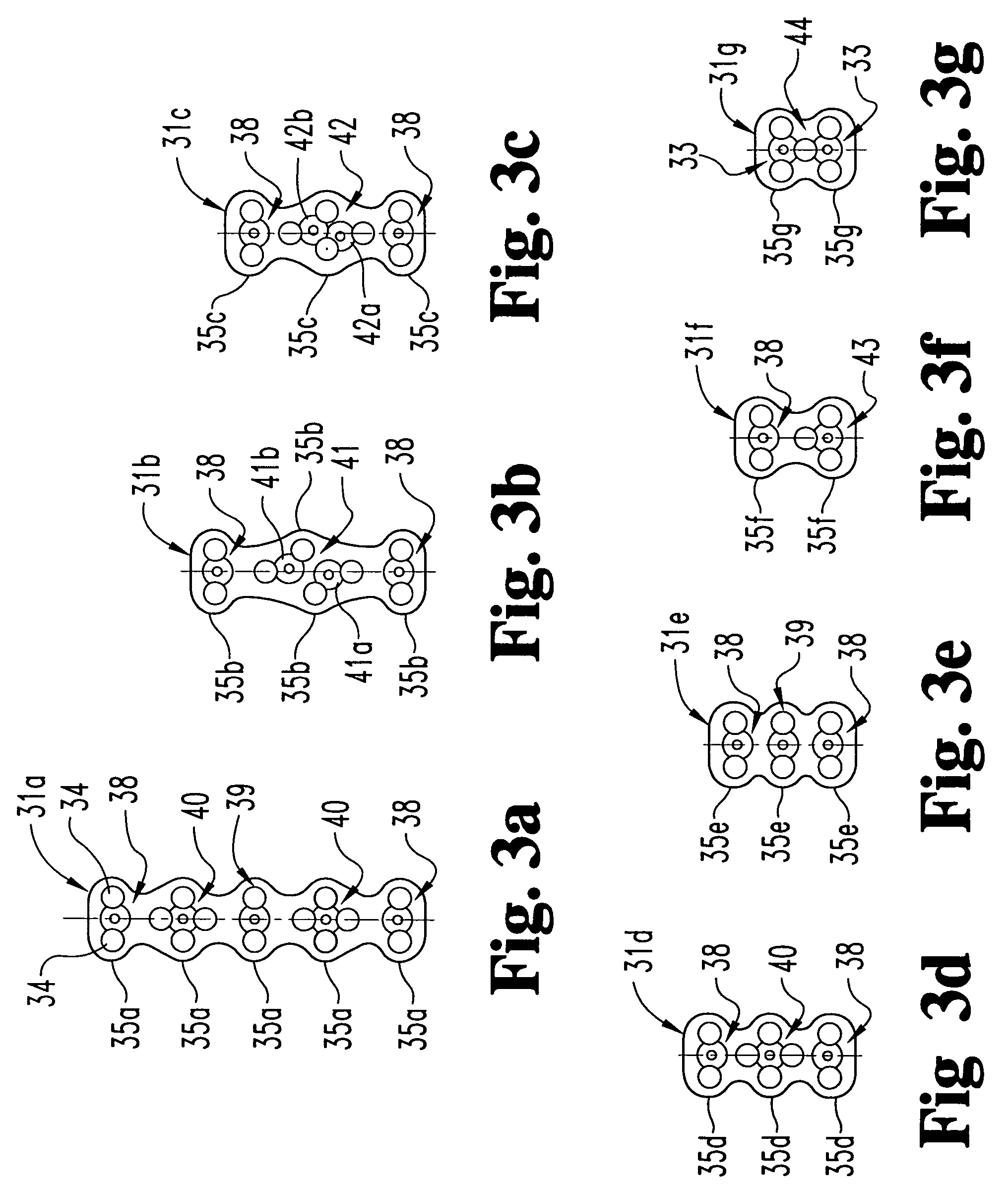
[0047]An anterior plating system or fixation assembly 30 is depicted in FIGS. 1 and 2. In accordance with the present invention, the plating system includes an elongated plate 31 and a number of bone screws 32. The bone screws are held to the plate 31 by way of a plurality of locking assemblies 33. The elongated plate 31 is provided with a plurality of screw holes 34 in a variety of arrangements. The plate also can be di...


PUM


Abstract

In one embodiment of the invention, an anterior fixation system includes a plate defining a plurality of screw holes, a number of screws and a number of locking assemblies for fixing the screws to the plate. The system includes two bone screws a fixed angle screw and a variable angle screw, that are configured to extend through the same screw openings in the fixation plate. The surgeon can select either the fixed or variable angled screws to be implanted with a single plate and can place either type of screw into any of the screw holes along the plate. The fixation plate according to the invention can include several screw holes in various patterns that provide the surgeon with great flexibility in the placement of bone screws depending upon the spinal anatomy and pathology. The invention further contemplates a locking assembly to lock one or more bone screws within a respective screw hole. In one embodiment, the locking assembly includes a washer that is held to the plate by a staked locking screw. The washer includes an outer surface that overlaps one or more screw holes. The washer is initially loosely held to the plate by the locking screw so that various tools and bone screws can be passed through the screw holes. In one embodiment of the washer, the washer includes cut-outs corresponding to the screw holes, along with a notch and key configuration for setting the locking washer in its locked configuration.

Description

CROSS REFERENCE TO RELATED APPLICATIONS[0001]This application is a continuation of U.S. patent application Ser. No. 09 / 723,317 filed on Nov. 27, 2000, now issued as U.S. Pat. No. 6,669,700 and which is incorporated herein by reference; which is a continuation of U.S. patent application Ser. No. 09 / 399,525 filed on Sep. 20, 1999, and now issued as U.S. Pat. No. 6,152,927; which is a continuation of U.S. patent application Ser. No. 08 / 856,902 filed on May 15, 1997, now abandoned.BACKGROUND OF THE INVENTION[0002]The present invention concerns spinal instrumentation systems, most particularly for use in fixation of the cervical spine. More particularly, the invention pertains to a plating system for use in the treatment of various spinal pathologies.[0003]As with any bony structure, the spine is subject to various pathologies that compromise its load bearing and support capabilities. The spine is subject to degenerative diseases, the effects of tumors and, of course, fractures and dislo...

Claims


Application Information

Patent Timeline
Patent Type & Authority Patents(United States)
IPC IPC(8): A61B17/80A61B17/58A61B17/70
CPCA61B17/7059A61B17/8042A61B17/8033A61B17/8047
Inventor FARRIS, ROBERT A.POYNER, JEFFREY WADESONNTAG, VOLKER K. H.HAID, JR., REGIS W.PAPADOPOULOS, STEPHEN M.
Owner SDGI HLDG
Why Eureka
Try Eureka