Laser assisted machining method and device

Active Publication Date: 2006-02-21
IND TECH RES INST
View PDF4 Cites 44 Cited by
  • Summary
  • Abstract
  • Description
  • Claims
  • Application Information

AI Technical Summary

Benefits of technology

[0006]It is still another objective of the present invention to provide a laser assisted machining device comprising a digital thermometer which is disposed in a tool handle or tool mount. The digital thermometer is used to monitor the temperature of the tool tip in such a way that the data are transmitted to a system controller, by which an automati

Problems solved by technology

The temperature of the tool tip at work can be therefore confined to a specific

Method used


Image

  • Laser assisted machining method and device
  • Laser assisted machining method and device
  • Laser assisted machining method and device

Examples


Example

[0018]The laser assisted machining method embodied in the present invention includes a fine machining process and an ultrafine machining process, which are described hereinafter with reference to FIGS. 2–10.

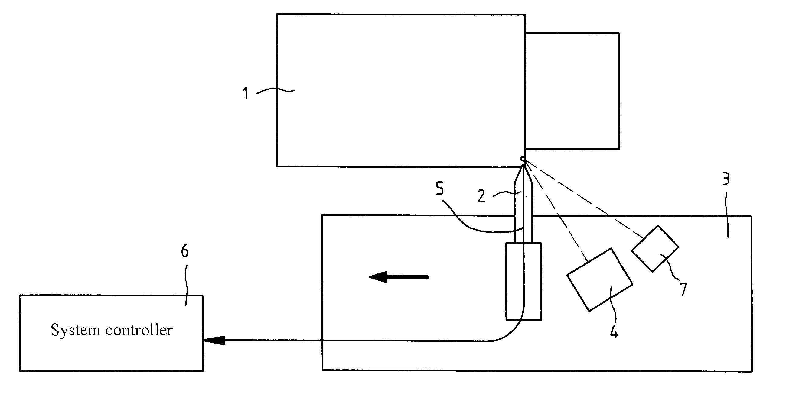
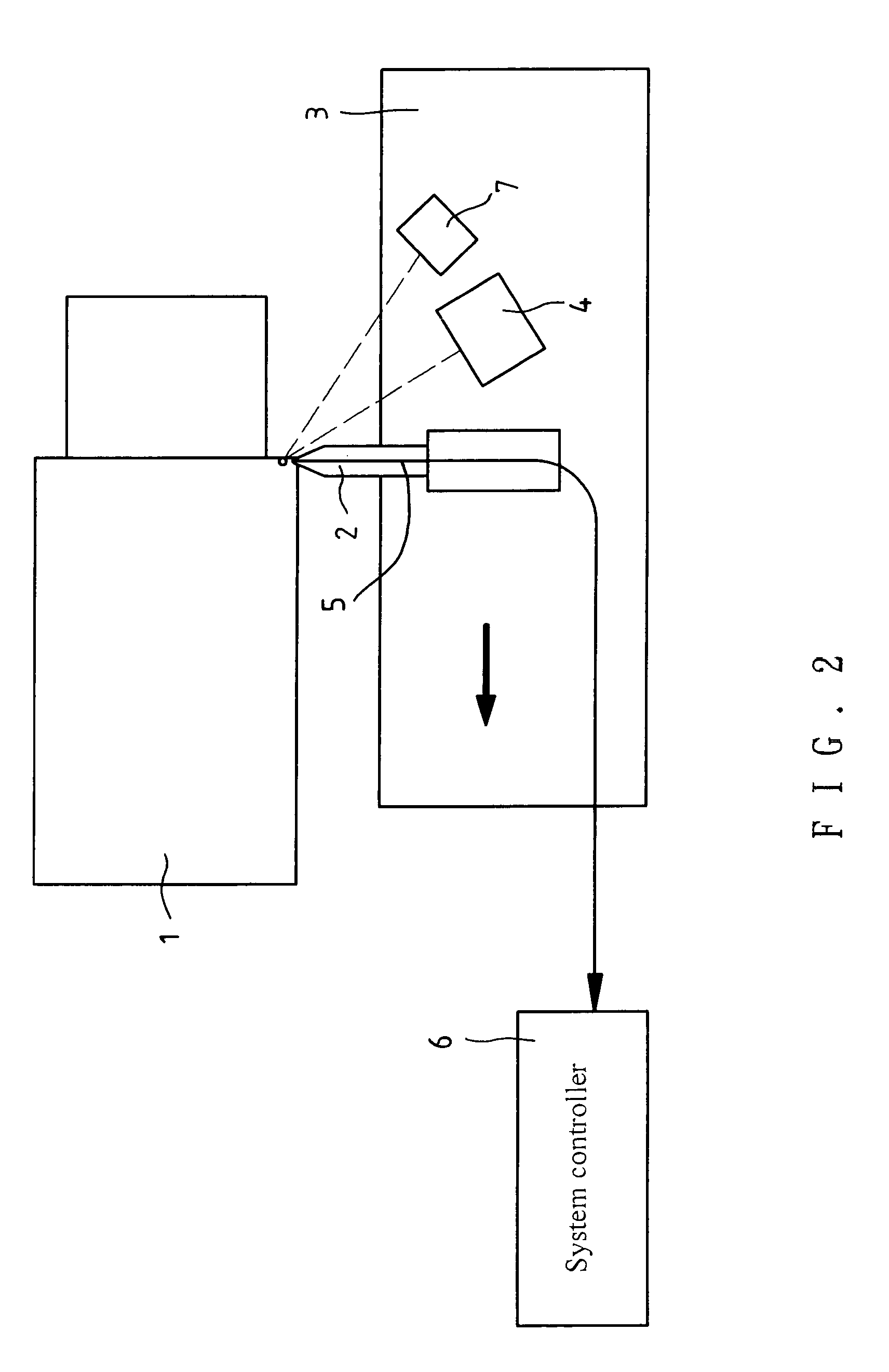
[0019]As illustrated in FIGS. 2 and 3, the method of the present invention involves the use of a pulse laser, by which a workpiece is heated intermittently and locally, the fine machining process of the present invention involves a workpiece 1, which is held by the chuck of a machinery, such as lathe, milling machine, etc. A machining tool 2 is disposed on a tool mount 3 on which a pulse laser head 4 and a chip spray 7 are located. The laser beam is brought into focus in front of the blade of the machining tool 2 such that the focal point is separated from the blade of the machining tool 2 by a distance ranging from several μm to several mm. In another words, the focal point is separated from a heating area “A” by the distance. There is a microdistance in front of the blade, whic...


PUM

PropertyMeasurementUnit
Lengthaaaaaaaaaa
Lengthaaaaaaaaaa
Temperatureaaaaaaaaaa

Abstract

A laser assisted machining method and device comprise a tool mount on which a laser head is disposed. A digital thermometer is disposed in a machining tool or on the tool mount for feeding data to a system controller. A laser is used to enable the blade of the machining tool to heat and soften a workpiece instantaneously. As the machining process is in progress, the chip is rapidly removed. The temperature of the tool tip is monitored by the digital thermometer for automatic control of the temperature of heating the workpiece by the laser, thereby keeping the temperature of the tool tip in a specific allowable range. The efficiency of the machining process and the surface precision are thus enhanced.

Description

FIELD OF THE INVENTION[0001]The present invention relates generally to a high speed precision machining process, and more particularly to a laser assisted method and a laser assisted device, which are designed to alleviate the tool wear, to enhance the removal rate of the machining chip and the surface precision of work piece, and to prolong the service life span of the tool.BACKGROUND OF THE INVENTION[0002]Certain materials, such as ceramics, glass, nickel superalloy, etc., can not be easily machined. The machining of such materials often results in tool wear in addition to poor surface precision of the work piece. For example, the machining of the ceramic material takes various forms, such as grinding, ultrasonic machining, laser machining, discharge machining, ion beam machining, etc. These various forms of the ceramics machining have their own advantages and disadvantages; nevertheless, they have one thing in common in poor removal rate of chip. If the machining of a ceramic mat...

Claims


Application Information

Patent Timeline
IPC IPC(8): B23K26/00B23K26/14B23K26/16B23K26/18B23K26/08B23K28/02B23K37/02B23P25/00
CPCB23K26/0093B23K26/0823B23P25/006B23K37/0229B23K28/02
Inventor WU, JINN-FAGUU, YEOU-BIN
Owner IND TECH RES INST
Why Eureka
Try Eureka