Method for bonding a pellicle to a patterning device and patterning device comprising a pellicle

Active Publication Date: 2006-05-25
ASML NETHERLANDS BV +1
View PDF5 Cites 7 Cited by
  • Summary
  • Abstract
  • Description
  • Claims
  • Application Information

AI Technical Summary

Benefits of technology

[0005] It is desirable to provide a method for bonding a pellicle on a patterning device for use with a lithographic apparatus whereby

Problems solved by technology

For example, a non flat pellicle membrane shape may cause out of tolerance image errors of an image of the pattern, as projected onto the substrate.
These image errors comprise optical aberrations such as, for example, distortion and defocus.
Attachment of a pellicle to a reticle may also cause deformations of the reticle, which in turn cause similar image errors.
For increasing Numerical Aperture (NA) of the projec

Method used


Image

  • Method for bonding a pellicle to a patterning device and patterning device comprising a pellicle
  • Method for bonding a pellicle to a patterning device and patterning device comprising a pellicle
  • Method for bonding a pellicle to a patterning device and patterning device comprising a pellicle

Examples


Example

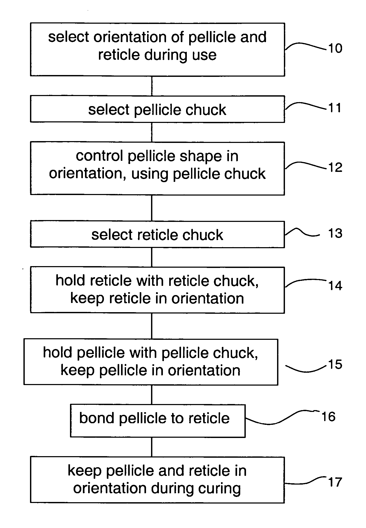
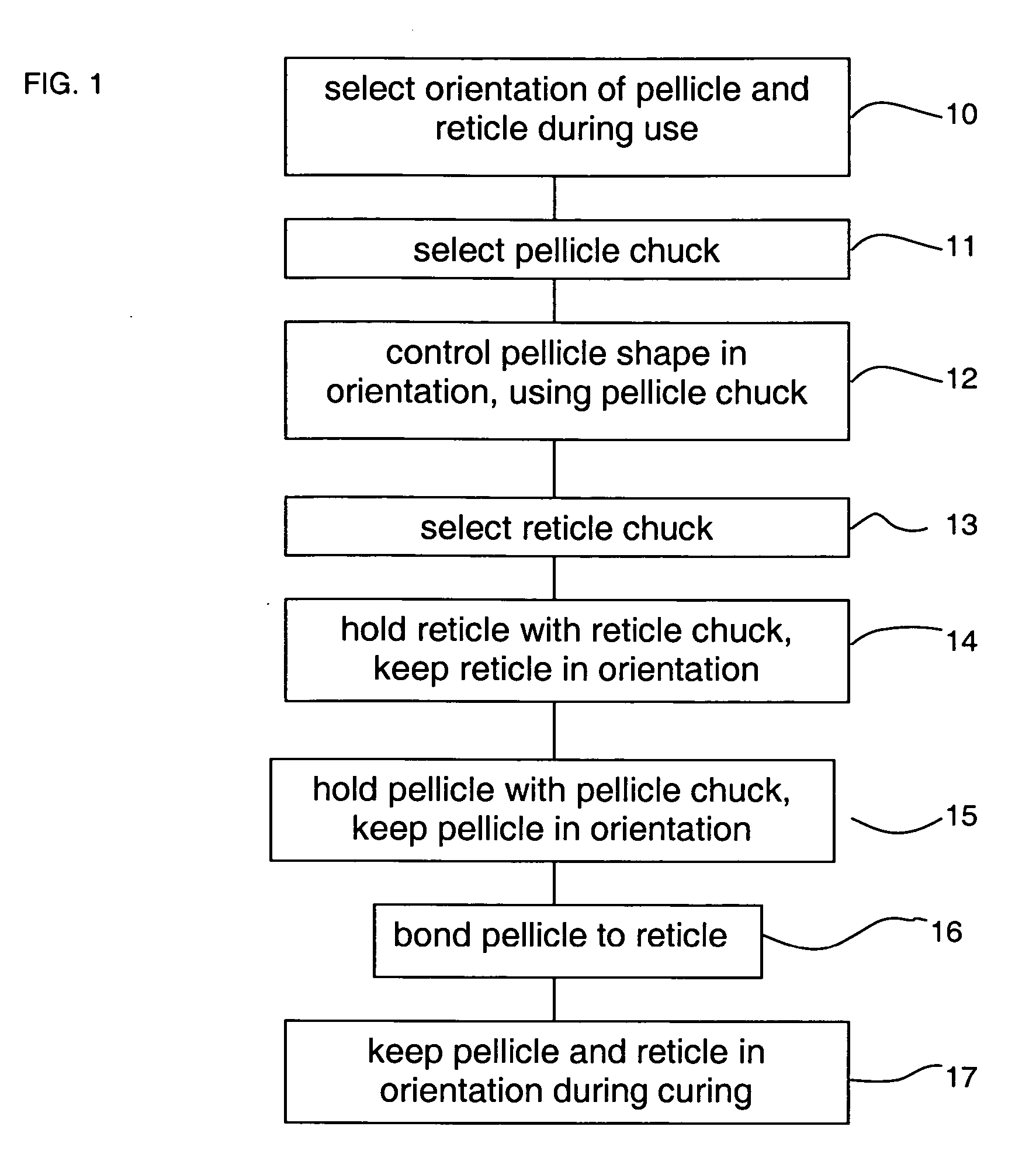
[0017] A pellicle for use with a reticle is bonded to a reticle at a bonding site separate from the lithographic apparatus. In addition to tooling for bonding the pellicle to the reticle, appropriate tooling for the qualification of the shape of the pellicle surfaces within said radiation transmissive area is used for the manufacture and quality control of the pellicle. Before bonding, both the reticle shape and pellicle shape are within tolerance in accordance with specifications defining maximum allowable deviations from nominal shape of the reticle and pellicle surfaces. After said bonding, a qualification of surface shapes of the reticle and pellicle is executed using, for example, an interferometer. Generally, a lithographic apparatus is embodied such that in use a patterning device, such as for example a reticle, is held in a horizontal orientation by a support constructed to support the patterning device or reticle. However, in principle, the orientation of a reticle during u...


PUM

PropertyMeasurementUnit
Size distributionaaaaaaaaaa
Sizeaaaaaaaaaa
Shapeaaaaaaaaaa

Abstract

A method is provided to reduce differences between the way in which reticle chucking forces and gravity force act upon the reticle during use and during assembly of the pellicle, and to combine this with a similar reduction concerning pellicle chucking forces and gravity force acting upon the pellicle during bonding to the reticle and during quality control of the pellicle. The shape of the pellicle is measured for control in the same orientation of the pellicle with respect to gravity force as during use of the pellicle, and during bonding the pellicle and the reticle are held in the same way and in the same orientation as during control of the pellicle and use of the reticle in the lithographic apparatus, respectively.

Description

FIELD [0001] The present invention relates generally to patterning devices for use with a lithographic apparatus and to pellicles for use therewith. BACKGROUND OF THE INVENTION [0002] A lithographic apparatus is a machine that applies a desired pattern onto a substrate, usually onto a target portion of the substrate. A lithographic apparatus can be used, for example, in the manufacture of integrated circuits (ICs). In that instance, a patterning device, which is alternatively referred to as a mask or a reticle, may be used to generate a circuit pattern to be formed on an individual layer of the IC. This pattern can be transferred onto a target portion (e.g. comprising part of, one, or several dies) on a substrate (e.g. a silicon wafer). Transfer of the pattern is typically via imaging onto a layer of radiation-sensitive material (resist) provided on the substrate. In general, a single substrate will contain a network of adjacent target portions that are successively patterned. Known...

Claims


Application Information

Patent Timeline
IPC IPC(8): G03B27/62
CPCY10T156/10G03F1/64
Inventor BRULS, RICHARD JOSEPHLAGANZA, JOSEPH L.UITTERDIJK, TAMMOBOOM, HERMAN
Owner ASML NETHERLANDS BV
Why Eureka
Try Eureka