

Electric motor, particularly an electronically commutated direct current motor
- Summary
- Abstract
- Description
- Claims
- Application Information
AI Technical Summary
Benefits of technology
Problems solved by technology
Method used
Image

Examples
Embodiment Construction
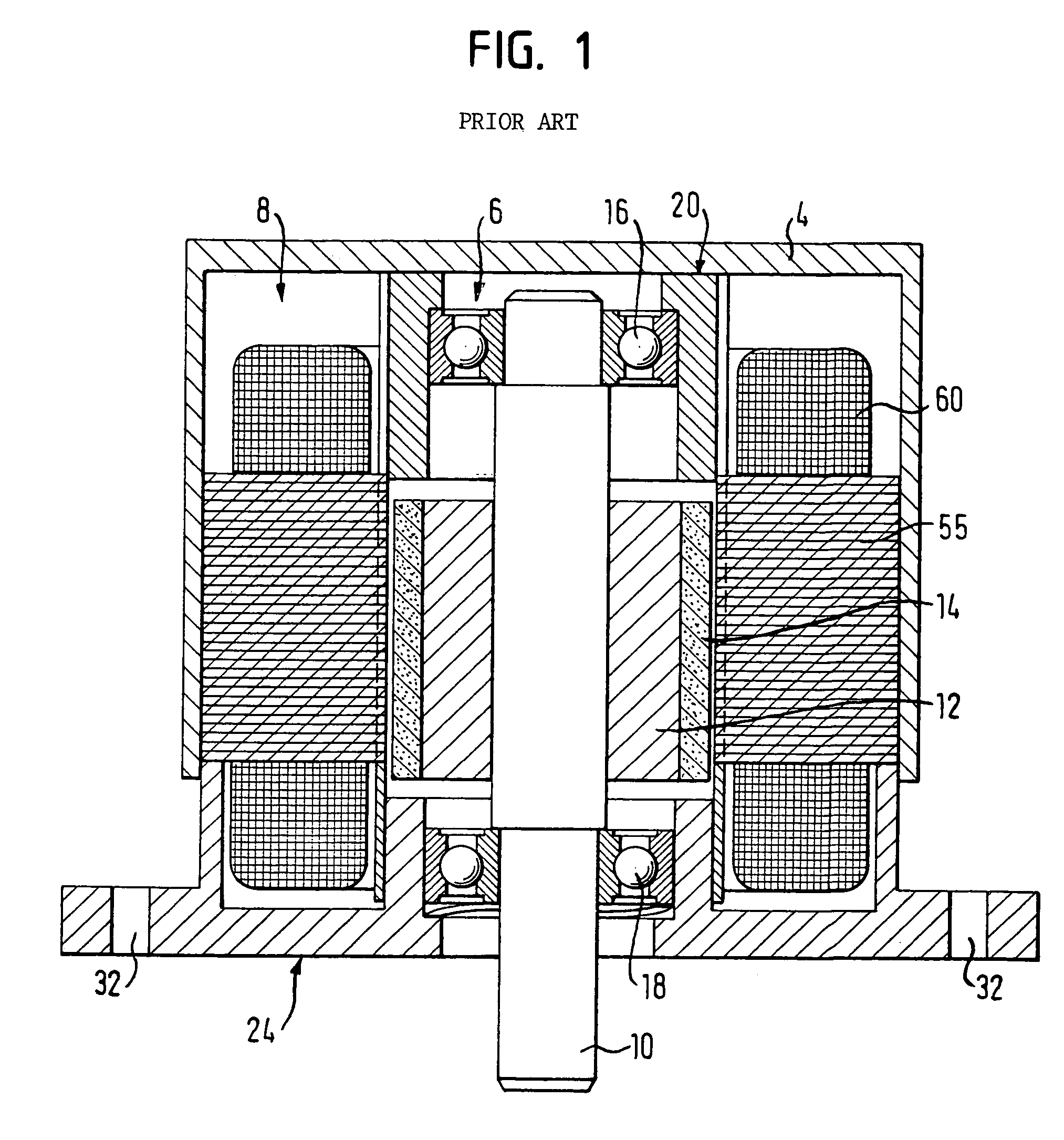
[0034]FIG. 1 shows the basic construction of an electronically commutated direct current motor in accordance with an inner rotor design of the prior art. The motor includes a rotor assembly 6 and a stator assembly 8. The rotor assembly 6 features a rotor shaft 10 which bears a coil flux guide (back iron ring) 12 made of a soft magnetic material such as iron. A segmented or annular permanent magnet 14 is mounted on the coil flux guide or back iron 12. The shaft 10 is rotatably supported by bearings 16, 18. The rotor assembly 6, shown in FIG. 1 with the rotor shaft 10, the back iron 12 and the permanent magnet(s) 14, is located within the stator assembly 8, illustrated by a stator stack provided with windings 60 and consisting of a number of stator plates 55. The stator is connected to a flange 24, wherein the rotor assembly 6 is supported within the flange 24 by the bearing 18 and within an end cap 20 by the bearing 16. The flange 24 and the sealing cap 20 are connected to a motor ho...
PUM
 Abstract
Description
Claims
Application Information