Liquid crystal display apparatus operating at proper data supply timing

a liquid crystal display and data supply technology, applied in static indicating devices, non-linear optics, instruments, etc., can solve the problems of signal distortion bringing about timing differences, reducing data write timing at the positions nearer to the gate driver, and more distorted gate signals

Inactive Publication Date: 2006-02-21
SHARP KK
View PDF7 Cites 11 Cited by
  • Summary
  • Abstract
  • Description
  • Claims
  • Application Information

AI Technical Summary

Benefits of technology

[0020]In the circuit described above, the display data is output to the next stage in synchronization with the clock signal used inside the data driver. This makes it possible to drive data drivers at proper timings regardless of delays and signal distortions that vary depending on the lengths of wires in the panel.

Problems solved by technology

When the gates are driven, the farther away from the gate drivers, the more distorted the gate signal will be because of the resistance and capacitance of the gate bus lines.
The signal distortion brings about timing differences between the positions nearer to the gate drivers and the positions farther away from the gate drivers.
Such setting, however, ends up reducing the data write timing at the positions nearer to the gate drivers.
As liquid crystal display panels are manufactured with an increasingly fine resolution, the horizontal cycle shortens, resulting in the difficulties in securing a sufficient data write time.
Also, as the liquid crystal display panels are manufactured with an increasingly large panel size, the gate bus lines are elongated, thereby making the effect of gate signal distortion increasingly conspicuous.
The finer and larger the liquid crystal display panels, therefore, the more difficult it is to secure a sufficient data write time.
This may result in a certain type of a liquid crystal display panel suffering a write failure.

Method used


Image

  • Liquid crystal display apparatus operating at proper data supply timing
  • Liquid crystal display apparatus operating at proper data supply timing
  • Liquid crystal display apparatus operating at proper data supply timing

Examples


first embodiment

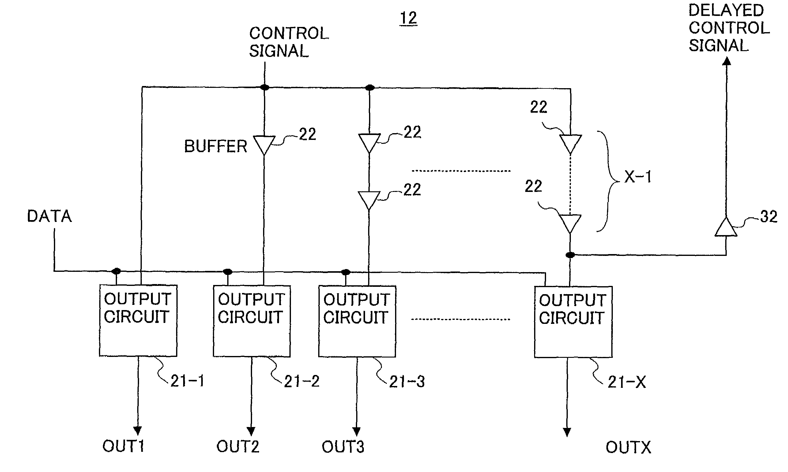
[0052]FIG. 4 is a drawing showing the data driver 12 according to the present invention.

[0053]The data driver 12 of FIG. 4 includes X output circuits 21-1 through 21-X and a plurality of buffers (delay elements) 22. Each output circuit receives data and a control signal, and outputs data (i.e., the liquid crystal drive voltage) to a data bus line 14 in accordance with the timing of an arrival of the control signal. At the control signal input of each output circuit, a predetermined number of buffers are provided according to the distances from the gate drivers 11 to the corresponding data bus line 14.

[0054]The output circuit 21-1 that corresponds to the data bus line 14 closest to the gate drivers 11 does not have an associated buffer 22, and the output circuit 21-2 that corresponds to the data bus line 14 second closest to the gate drivers 11 has one associated buffer 22. Further, the output circuit 21-3 corresponding to the data bus line 14 third closest to the gate drivers 11 has...

third embodiment

[0065]FIG. 11 is a drawing showing the data driver 12 according to the present invention.

[0066]In the data driver 12 of FIG. 11, the output circuits 21-2 through 21-X each have a control signal input thereof coupled to a circuitry that includes a two-input AND circuit 41, a two-input AND circuit 42 having a negative logic input at one input thereof, an OR circuit 43, and a plurality of buffers (delay elements) 51. A selection signal is supplied to one input of the two-input AND circuit 41, and is supplied to the negative logic input of the two-input AND circuit 42.

[0067]When the selection signal is HIGH, the control signal supplied through the series of buffers 51 connected to the two-input AND circuit 41 is fed to a corresponding output circuit. When the selection signal is LOW, the control signal supplied through the series of buffers 51 connected to the two-input AND circuit 42 is fed to a corresponding output circuit. The number of buffers 51 connected to the two-input AND circu...


PUM

PropertyMeasurementUnit
conductiveaaaaaaaaaa
resistanceaaaaaaaaaa
capacitanceaaaaaaaaaa

Abstract

A circuit for driving a liquid crystal display panel includes a plurality of output circuits that are coupled to respective data bus lines of the liquid crystal display panel, and output liquid crystal drive signals to the respective data bus lines with respective delays that progressively increase from a first one of the data bus lines to a last one of the data bus lines.

Description

BACKGROUND OF THE INVENTION[0001]1. Field of the Invention[0002]The present invention relates to a liquid crystal panel drive circuit and a liquid crystal display apparatus.[0003]2. Description of the Related Art[0004]In a liquid crystal display panel, pixels including transistors are arranged in rows and columns, with gate bus lines extending in the horizontal direction being connected to the gates of the pixel transistors, and data bus lines extending in the vertical direction being connected to the pixel capacitors. When data is to be displayed on the liquid crystal display panel, gate drivers drive the gate bus lines one after another to make transistors conductive on a successive line, and the data drivers write the data of one horizontal line to the pixels through the turned-on transistors.[0005]When the gates are driven, the farther away from the gate drivers, the more distorted the gate signal will be because of the resistance and capacitance of the gate bus lines. The signa...

Claims


Application Information

Patent Timeline
Patent Type & Authority Patents(United States)
IPC IPC(8): G09G3/36G02F1/133G09G3/20
CPCG09G3/3688G09G2320/0223G02F1/133
Inventor SEKIDO, SATOSHI
Owner SHARP KK
Why Eureka
Try Eureka