Wide-band dispersion controlled optical fiber

a wide-band dispersion control and optical fiber technology, applied in the field of optical fibers, can solve the problems of raman amplification efficiency decline, inefficient construction of a wide-band communication network using a single-mode optical fiber, and increased cost of compensating dispersion in wdm mod

Active Publication Date: 2006-02-21
SAMSUNG ELECTRONICS CO LTD
View PDF22 Cites 24 Cited by
  • Summary
  • Abstract
  • Description
  • Claims
  • Application Information

AI Technical Summary

Benefits of technology

[0017]Accordingly, the present invention has been made to reduce or overcome the above-mentioned limitations occurring in the prior art. One object of the present invention is to provide a wide-band dispersion controlled optical fiber which is capable of transmitting optical signals of various wavelength regions and a wide-band dispersion controlled optical fiber which enables not only short distance transmission but also middle/long distance transmission using one type of optical fiber.
[0018]In accordance with the principles of the present invention a wide-band dispersion controlled optical fiber is provided, characterized in that the fiber is controlled/tuned, using respective core and clad diameters and distribution of refractive indexes, to have (1) the position of the zero dispersion wavelength, and (2) negative dispersion values in the O-band wavelength region and positive dispersion values with small deviations in the C-band and

Problems solved by technology

As a result, the cost is increased for compensating dispersion in WDM mode.
Therefore, it is not efficient to construct a wide-band communication network using a single mode optical fiber in a WDM communication network.
Furthermore, there is a problem in that if the effective cross-section area increases, Raman amplification efficiency decreases.
However, because the zero dispersion wavelength of a positive dispersion optical fiber is located in the wavelength region of 1460 nm to 1500 nm as indicated by the second and third curves, it is impossible to use Raman amplification which is used in long distance transmission.
Because this induces a non-linear phenomenon such as FWM, it is not efficient to us

Method used


Image

  • Wide-band dispersion controlled optical fiber
  • Wide-band dispersion controlled optical fiber
  • Wide-band dispersion controlled optical fiber

Examples


Embodiment Construction

[0030]In the following description of the present invention, for purposes of explanation rather than limitation, specific details are set forth such as the particular architecture, interfaces, techniques, etc., in order to provide a thorough understanding of the present invention. However, it will be apparent to those skilled in the art that the present invention may be practiced in other embodiments that depart from these specific details. Moreover, it will be recognized that certain aspects of the figures are simplified for explanation purposes and that the full system environment for the invention will comprise many known functions and configurations all of which need not be shown here. In the drawings, the same or similar elements are denoted by the same reference numerals even though they are depicted in different drawings.

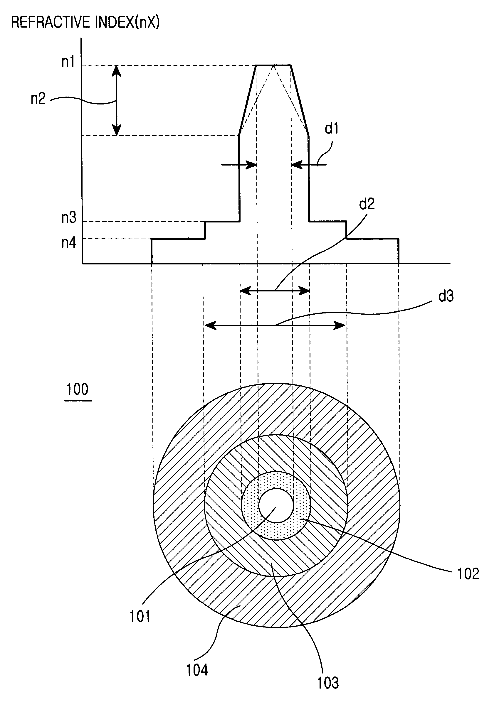
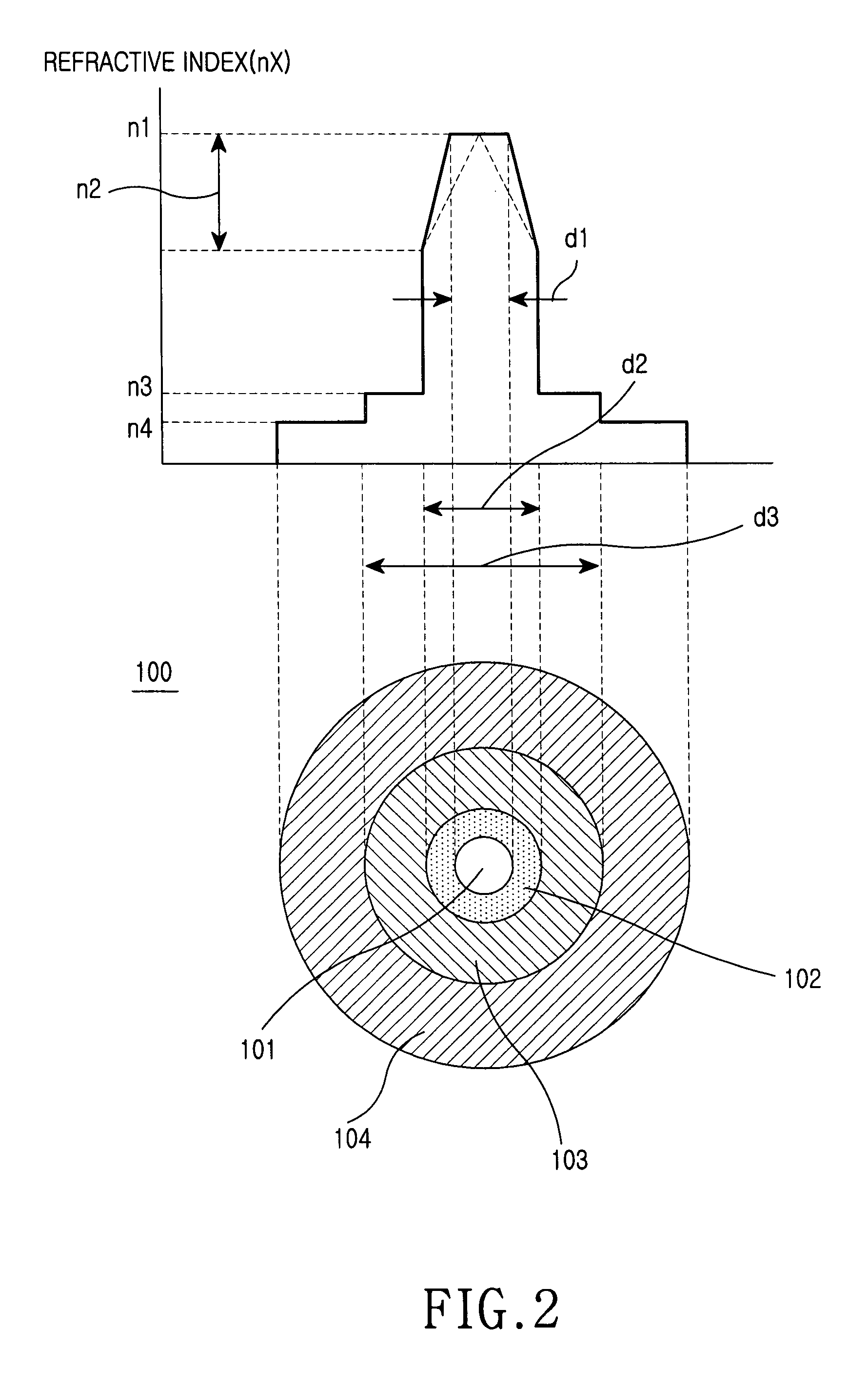
[0031]FIG. 2 is a wide-band dispersion controlled optical fiber 100 according to a preferred embodiment of the present invention and a graph showing the dist...


PUM


Abstract

Disclosed is a wide-band dispersion controlled optical fiber. The optical fiber enables the use of optical signals in various wavelength regions in a wavelength division multiplexing mode communication network by controlling the position of the zero dispersion wavelength, and enables long distance transmission by controlling dispersion slope and bending loss. Furthermore, there is an advantage in that the optical fiber enables not only short distance transmission but also middle/long distance transmission using a single type of optical fiber because the optical fiber is controlled to have negative dispersion values in the O-band wavelength region and positive dispersion values with small deviations in the C-band and L-band wavelength regions.

Description

CLAIM OF PRIORITY[0001]This application claims priority to an application entitled “Wide-band Dispersion Controlled Optical Fiber,” filed with the Korean Intellectual Property Office on Jan. 20, 2003 and assigned Ser. No. 2003-3770, the contents of which are hereby incorporated by reference.BACKGROUND OF THE INVENTION[0002]1. Field of the Invention[0003]The present invention relates to an optical fiber, and in particular to a wide-band dispersion controlled optical fiber which is capable of being used for medium / long distance transmission while using optical signals of wide wavelength band.[0004]2. Description of the Related Art[0005]In an optical communication network for transferring high capacity information in Wavelength Division Multiplexing (WDM) mode, N optical signals with different wavelengths are multiplexed and concurrently transmitted through one strand of an optical fiber. The C-band wavelength region (1530 nm to 1565 nm) and the L-band wavelength region (1570 nm to 160...

Claims


Application Information

Patent Timeline
IPC IPC(8): G02B6/02G02B6/00G02B6/036H01S3/067H01S3/30
CPCG02B6/02014G02B6/02223G02B6/02238G02B6/03633G02B6/0281H01S3/302H01S3/06725H01S3/06729G02B6/02
Inventor CHO, JEONG-SIKDO, MUN-HYUNYANG, JIN-SEONGCHA, SANG-HOHAN, JU-CHANGJANG, YUN-GEUNKWAK, KI-MOON
Owner SAMSUNG ELECTRONICS CO LTD
Why Eureka
Try Eureka