Infrared heating system for patio umbrella

a technology of infrared heating and umbrellas, which is applied in the field of heating systems, can solve the problem that the convection cannot be controlled only by air temperature and air speed

Inactive Publication Date: 2006-02-21
HNI TECH INC
View PDF27 Cites 45 Cited by
  • Summary
  • Abstract
  • Description
  • Claims
  • Application Information

AI Technical Summary

Problems solved by technology

Because most convection heating uses air as the medium for transferring the heat, convection can only be controlled by air temperature and air speed.

Method used


Image

  • Infrared heating system for patio umbrella
  • Infrared heating system for patio umbrella
  • Infrared heating system for patio umbrella

Examples


Embodiment Construction

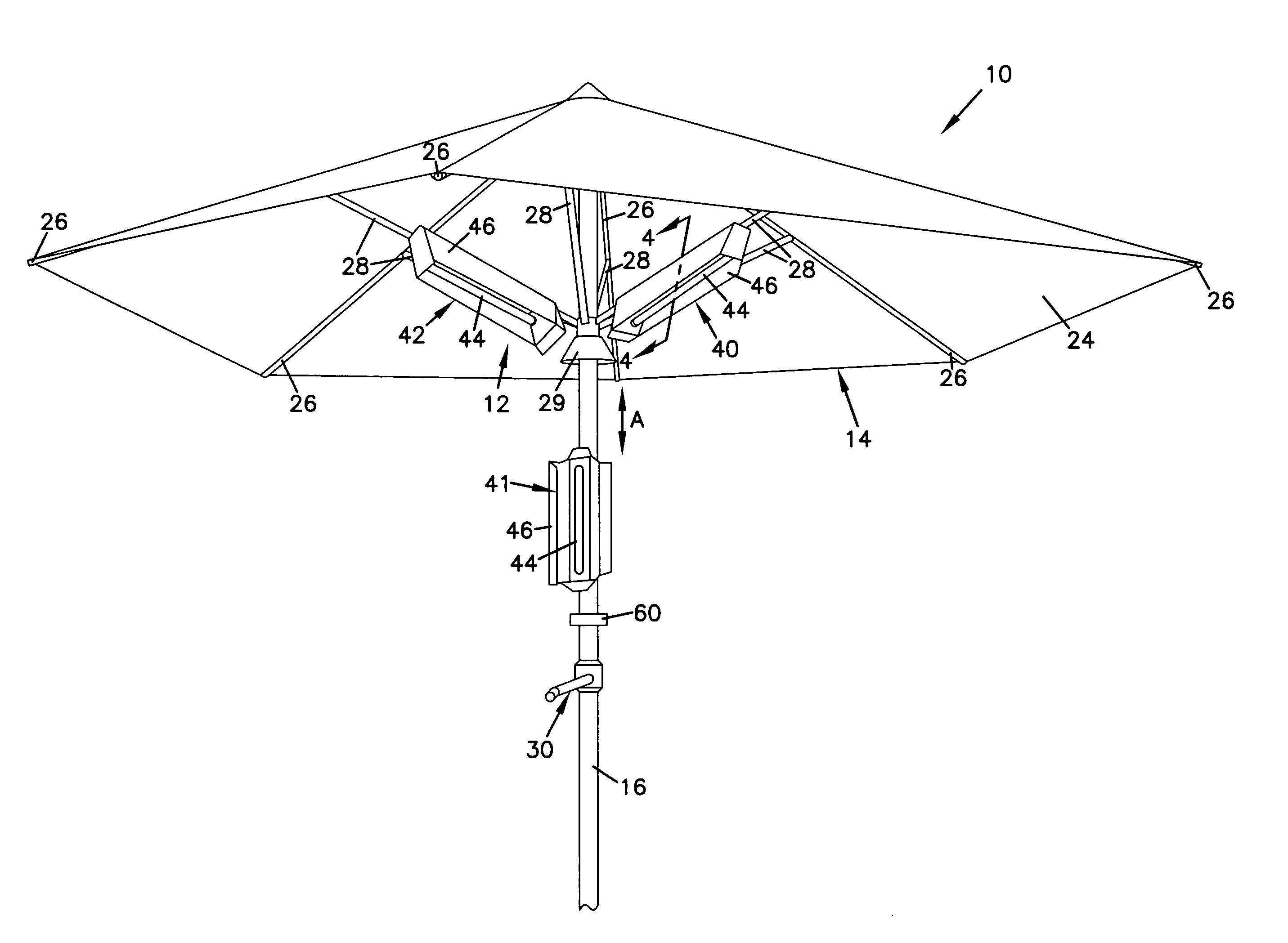
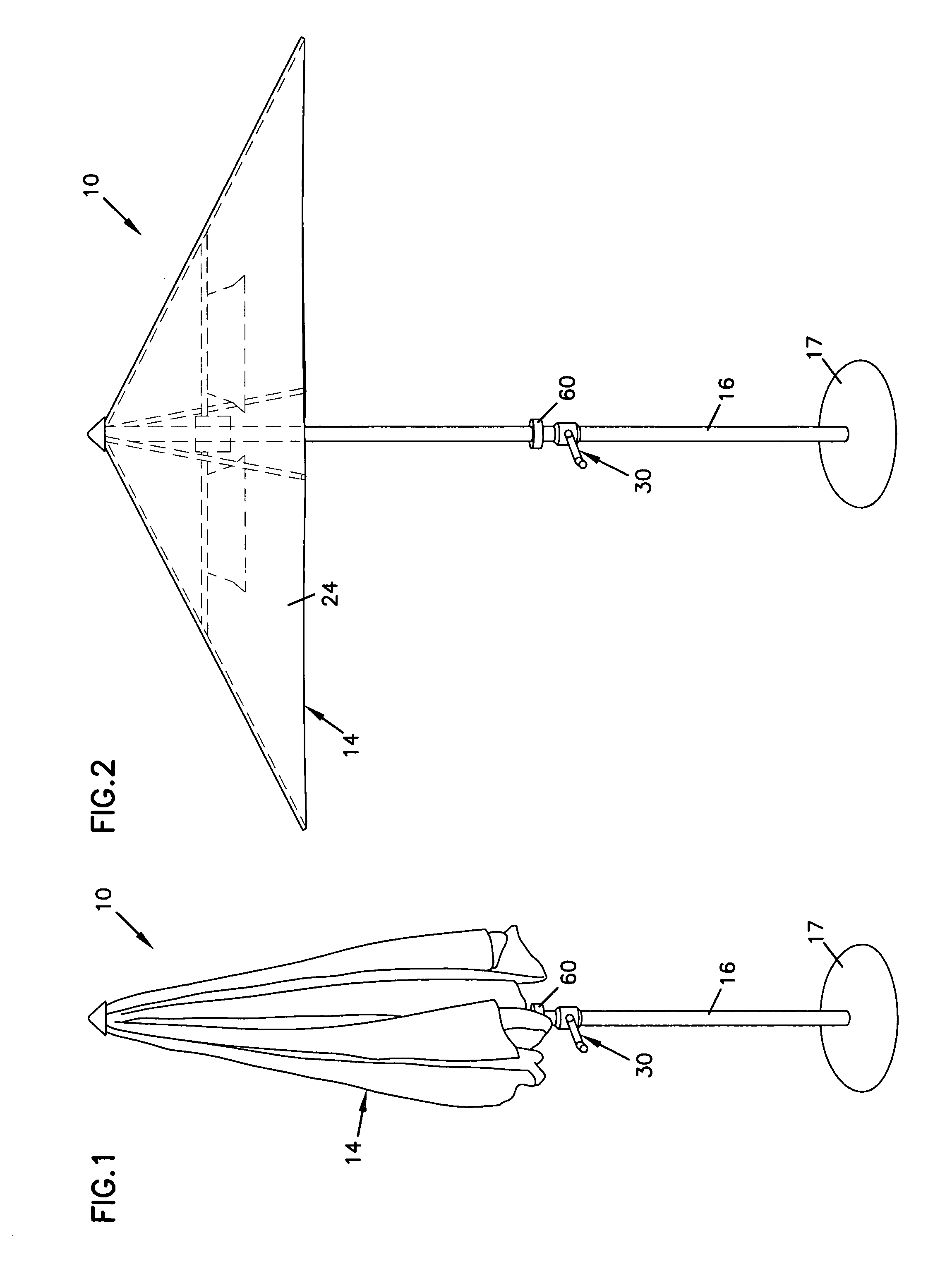
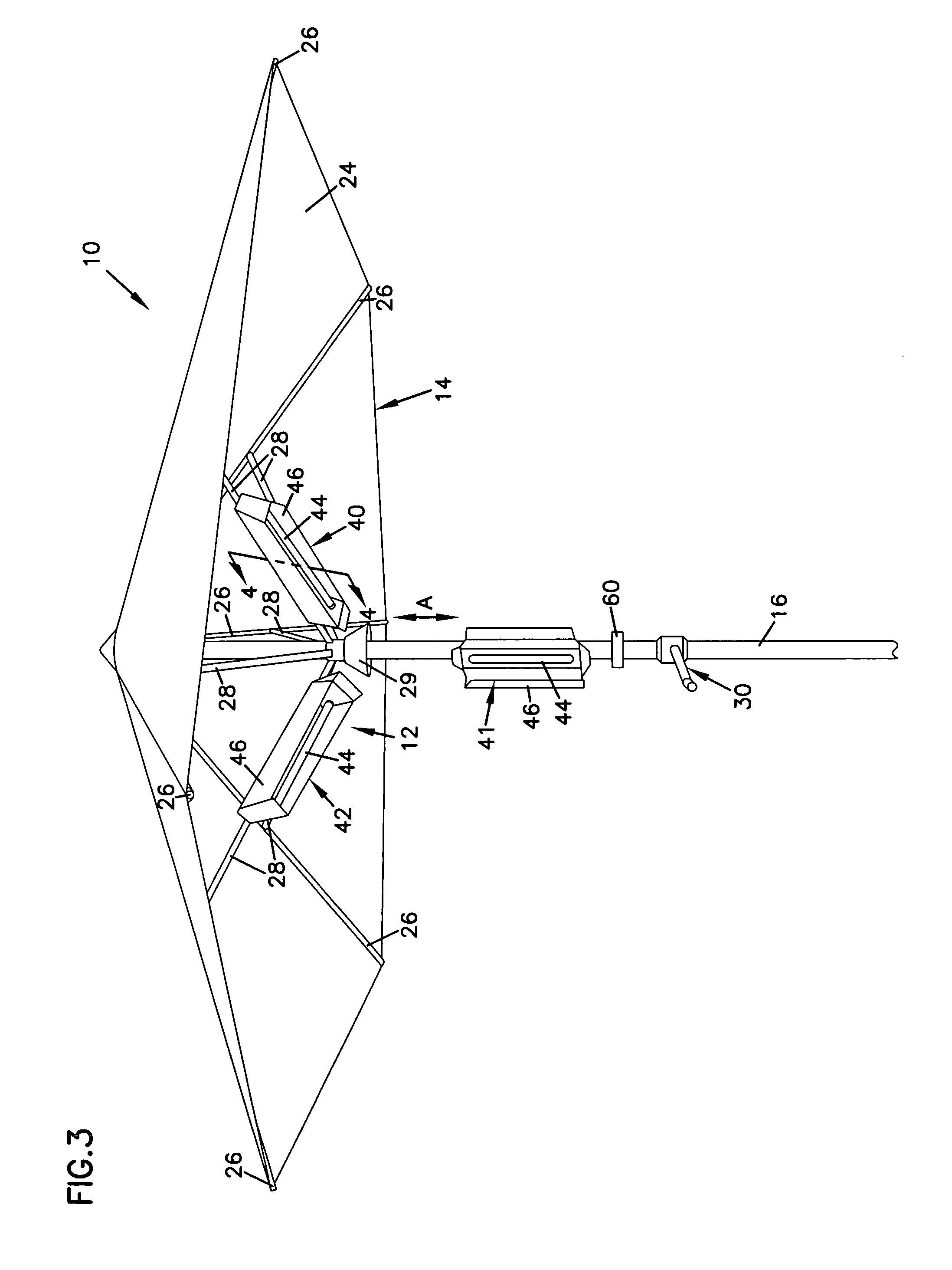
[0024]The present invention generally relates to heating systems, and more particularly relates to heating systems for umbrella-shaped structures. In one aspect of the invention, a heating system is mounted within an inner volume defined by a shroud. The heating system includes at least one infrared heating element positioned generally downward-facing in the inner volume of the shroud to direct heat at objects positioned generally below the shroud.

[0025]An infrared heating system may be particularly useful in combination with an outer patio umbrella or other outdoor shading structure. Infrared elements produce infrared waves that pass freely through air (without the air conducting an appreciable amount of heat from the waves) until the waves contact a physical object such as, for example, a person or an inanimate object such as a chair or table. When the object is contacted by the infrared waves, electrons in the object are excited and the object produces heat. The object then becom...


PUM


Abstract

The present invention relates to heating systems for umbrella-shaped structures. The heating system may include a shroud or umbrella-shaped structure defining an inner volume, and a plurality of electrical infrared heating elements positioned generally downward facing in the inner volume of the shroud. The shroud may include radially extending support structures to which the heating elements are mounted.

Description

BACKGROUND OF THE INVENTION[0001]1. Technical Field[0002]The present invention generally relates to heating systems, and more specifically relates to heating system for umbrella-shaped structures.[0003]2. Related Art[0004]Infrared heaters are well known and have been used for many years in various heating applications. Heating with infrared energy is often more efficient than convective forced air heating systems for several reasons. First, convection heating involves a gas (typically air) or liquid that transfers heat from one solid body to another. Because most convection heating uses air as the medium for transferring the heat, convection can only be controlled by air temperature and air speed. In contrast, infrared heating (which includes waves having wavelengths between about 0.75 microns to about 1000 microns) only heats objects and does not heat the air in space that it travels through. Air, the medium for convective heat, is a poor absorber of infrared heat, thus infrared he...

Claims


Application Information

Patent Timeline
Patent Type & Authority Patents(United States)
IPC IPC(8): A45B11/00H05B3/00A45B3/00A45B23/00A45B25/00F24C1/10F24C7/04F24C15/30F24D10/00F26B3/30
CPCA45B3/00F24C15/30A45B2200/1009A45B23/00
Inventor BACHINSKI, THOMAS J.HOLM, DOUGLAS MARK
Owner HNI TECH INC
Why Eureka
Try Eureka