
Procedure and device for control of data file transmission

a technology for data file transmission and control device, which is applied in the direction of electric digital data processing, multiple digital computer combinations, instruments, etc., can solve the problems of long transfer time, low transmission speed from a server to a receiving unit, and overloaded transmission units or transmission networks, so as to reduce the risk of transmission network overload

Inactive Publication Date: 2006-02-21
TELIASONERA
View PDF6 Cites 6 Cited by
  • Summary
  • Abstract
  • Description
  • Claims
  • Application Information

AI Technical Summary

Benefits of technology

[0005]Consequently one aim of the invention is to create a procedure, and a corresponding device, for control of data file transmission that reduces the risk of overload of transmitting units and transmission networks.
[0006]It is also an aim of the present invention to create a procedure, and a corresponding device, that makes a more efficient control of data file transmission between transmitting and receiving units.

Problems solved by technology

At transmission of data files from a transmitting unit, or a server, to a receiving unit, for instance over Internet, it frequently occurs that the transmitting unit, or the network that is utilized for the transmission, is overloaded.
This may result in that the transmission speed from a server to the receiving unit will be very low, which in its turn results in very long transfer times and also can result in that the transmission will be unsuccessful.
A problem in the situation is that the user or the receiving unit does not know which server, or which part of the network, that for the time being has a low load.
By that there also will be the risk that also this server is, or will be, overloaded and that the transmission is slowed down or has to be broken.
There also is a risk of imbalance of networks and servers.

Method used


Image

  • Procedure and device for control of data file transmission
  • Procedure and device for control of data file transmission
  • Procedure and device for control of data file transmission

Examples


Embodiment Construction

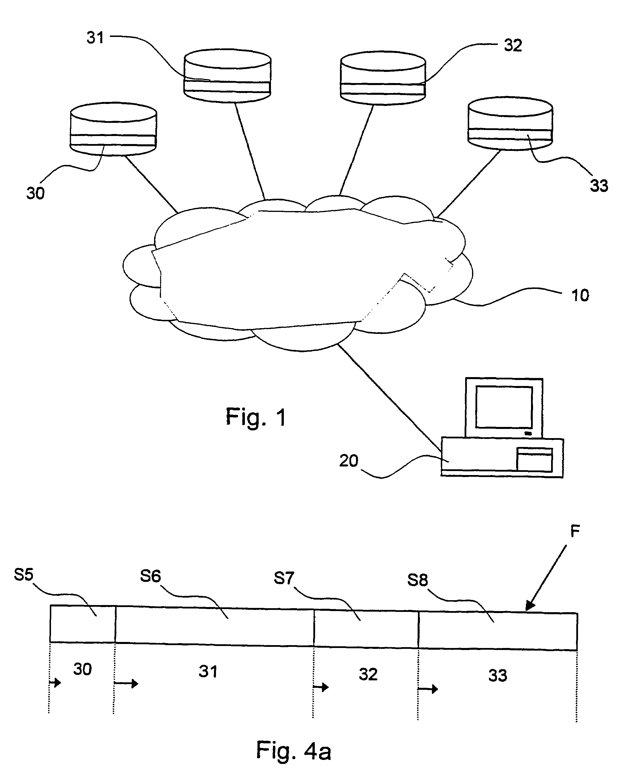
[0029]FIG. 1 shows diagrammatically a system to effect the procedure according to embodiments of the invention. The system includes a receiving unit or computer 20 and a number of transmitting units or servers 30, 31, 32, 33, which all are interconnected by connection to a network 10, which in preferred embodiments is constituted by Internet. With respective server 30, 31, 32, 33 is stored at least one example of a data file that one wants to have transmitted to the commuter 20. In order to facilitate the description, the number of illustrated servers has been limited to four, which should not be regarded as a limitation of, or recommmendation for, suitable number of servers.

[0030]Communication between computer and server is best performed according to standardized and well-known IP-protocols.

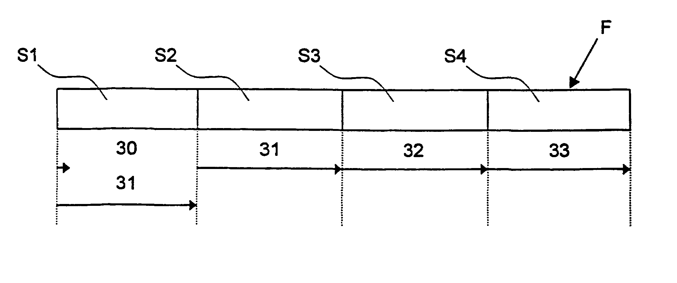
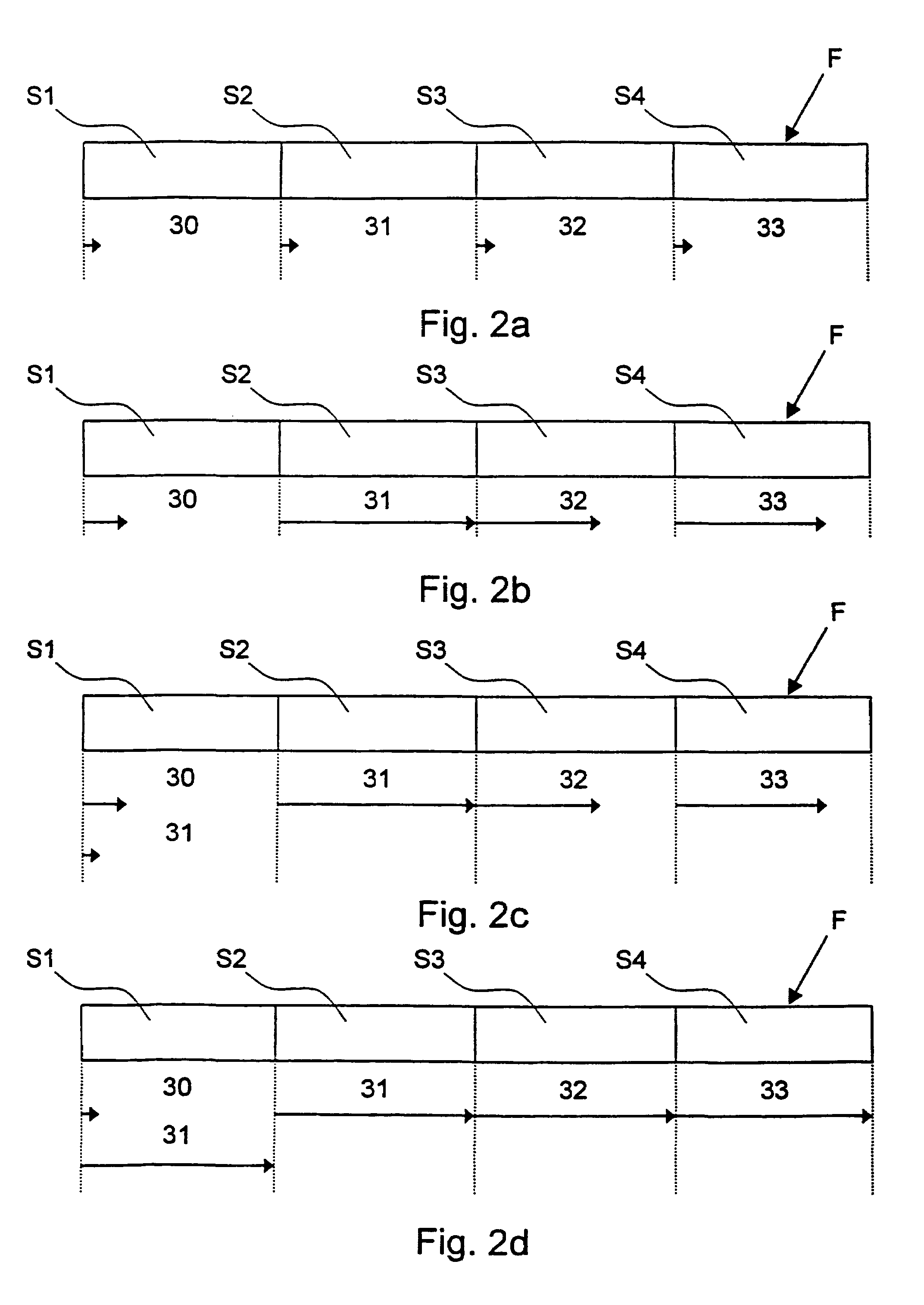
[0031]With reference to the FIGS. 2a–2b is diagrammatically shown an example of a course of events according to a preferred embodiment of a procedure according to the present invention. Accordi...


PUM


Abstract

A procedure for control of data file transmission between transmitting and receiving units, at which examples of the data file to be transmitted / transferred are stored at a plurality of the transmitting units, and a device to effect this procedure. The control of the data file transmission is performed according to the following procedure. Transmission of segments of the wanted data file from a plurality of transmitting units is requested, and these segments are received from the transmitting units. When the transmission of a segment of the data file from a first server is finished, transmission of one more segment of the data file is requested, for which transmission from another server has started but not been finished, from the first server. This is after that repeated until all segments have been transmitted, at which transmissions in progress are stopped and the segments are put together to the wanted file.

Description

FIELD OF THE INVENTION[0001]The invention relates to transmission of data files. More specifically the invention relates to a procedure for control of data file transmission between transmitting and receiving units, at which examples of the data file that shall be transmitted are stored at a plurality of units. The invention also relates to a device to perform this procedure.TECHNICAL BACKGROUND[0002]At transmission of data files from a transmitting unit, or a server, to a receiving unit, for instance over Internet, it frequently occurs that the transmitting unit, or the network that is utilized for the transmission, is overloaded. This may result in that the transmission speed from a server to the receiving unit will be very low, which in its turn results in very long transfer times and also can result in that the transmission will be unsuccessful.[0003]However, it is usual, i.a. on the Internet, that files are copied and distributed to a plurality of servers in order to share the ...

Claims


Application Information

Patent Timeline
Patent Type & Authority Patents(United States)
IPC IPC(8): G06F15/16H04L69/40
CPCH04L67/06H04L69/14H04L69/40
Inventor JOHANSSON, JOACHIMBERGSTEN, ANDERSBORG, NIKLAS
Owner TELIASONERA
Learn More