Display shelf

a technology for display shelves and shelves, applied in the field of beverage display shelves, can solve the problems of often less than optimal positioning, and achieve the effect of improving viewability

Inactive Publication Date: 2006-02-28
MECHTRONICS
View PDF11 Cites 108 Cited by
  • Summary
  • Abstract
  • Description
  • Claims
  • Application Information

AI Technical Summary

Benefits of technology

[0007]An advantageous signage carrier is unitarily molded with the main body below a floor portion thereof and is at an angle off vertical to improve viewability by a consumer looking downward through the door at the signage.

Problems solved by technology

This positioning is often less than optimal from the point of view of consumer visibility as relatively far from the hinged or sliding glass door of the case.

Method used


Image

  • Display shelf
  • Display shelf
  • Display shelf

Examples


Embodiment Construction

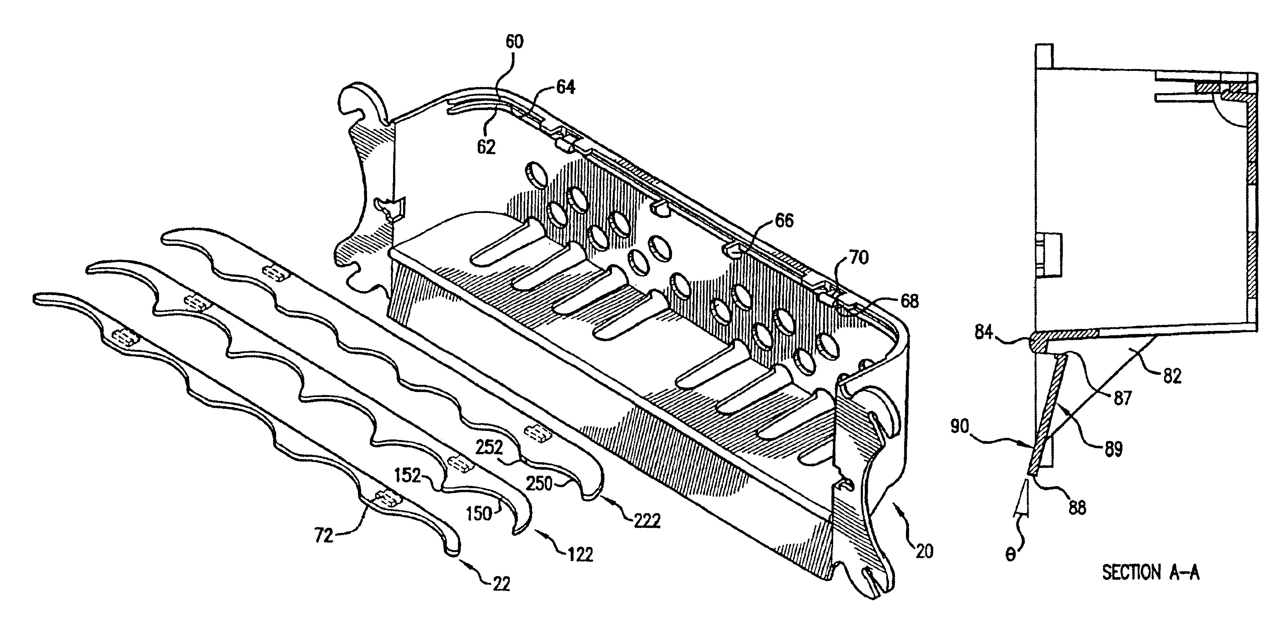
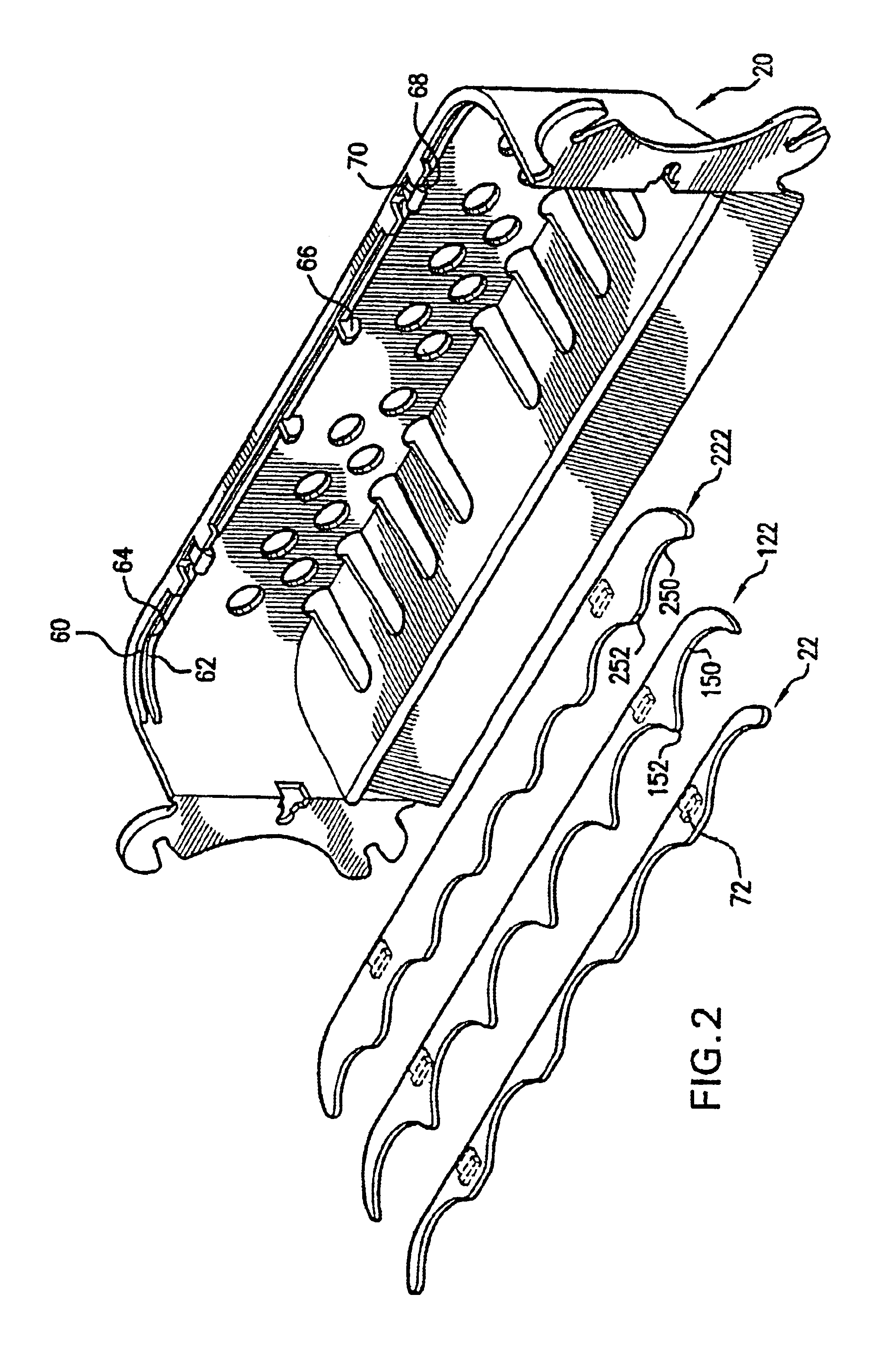
[0015]FIG. 1 shows an assembly of a display body 20 and adapter plate 22. The body 20 and adapter plate 22 advantageously each consist essentially of unitary moldings of plastic material (e.g., polyethylene terephthalate glycol (PET-G)). The material is advantageously transparent and untinted. In another embodiment, the material is tinted or colored for example to suit a particular branded scheme or to improve visibility.

[0016]The body 20 includes a lower wall or floor portion 24, a front wall portion 26 and left and right sidewall portions 28 and 30. Along rear edges of the sidewalls 28 and 30, associated left and right ears 32 and 34 extend laterally outward and have front and rear surfaces. The ears 32 and 34 each include a number of apertures 40 for receiving root ends of suction cups (not shown) for mounting the display to an interior surface of a glass wall of a refrigerator case door (also not shown). It should be appreciated that other means for mounting the display may be e...


PUM


Abstract

A bottle glorifier may be mounted on the interior surface of a glass refrigerator case door. A body holds a side-to-side array of exemplary containers. A separate adapter accommodates particular sizes or combinations of sizes of containers for a given body.

Description

CROSS-REFERENCE TO RELATED APPLICATIONS[0001]This patent application claims the benefit of U.S. Provisional Patent Application Ser. No. 60 / 375,483, entitled “GLORIFIER” that was filed on Apr. 24, 2002, the disclosure of which is incorporated by reference in its entirety as if fully set forth herein.BACKGROUND OF THE INVENTION[0002]1. Field of the Invention[0003]This invention relates to retail displays, and more particularly to the display of beverage containers in refrigerator cases.[0004]2. Description of the Related Art[0005]In the retail environment, beverages are often sold from refrigerator cases. The beverages are typically carried in front to back columns on shelves or shelf glides. This positioning is often less than optimal from the point of view of consumer visibility as relatively far from the hinged or sliding glass door of the case. It is accordingly advantageous to provide some form of rack or glorifier more prominently displaying representative beverage containers (e...

Claims


Application Information

Patent Timeline
Patent Type & Authority Patents(United States)
IPC IPC(8): A47F7/00A47F5/08A47F7/28B65DF25D23/04
CPCA47F7/28F25D2331/809F25D23/04
Inventor WALSH, DESMOND M.FELLINGER, RICHARD J.
Owner MECHTRONICS
Why Eureka
Try Eureka