
Water spray plate and shower head

a technology of water spray plate and shower head, which is applied in the direction of spray nozzle, spray apparatus, liquid spraying apparatus, etc., can solve the problems of increased manufacturing cost, inconvenience, and dispersed expansion of shower water,

Inactive Publication Date: 2006-02-28
OKUBO TAKAYASU
View PDF14 Cites 78 Cited by
  • Summary
  • Abstract
  • Description
  • Claims
  • Application Information

AI Technical Summary

Benefits of technology

[0014]It is a first object of the present invention to provide a water spray plate with which it is possible to obtain water-saving effects and a shower head employing the same.
[0015]It is a second object of the present invention to provide a water spray plate with which it is possible to generated minus ion by a large amount and a shower head employing the same.

Problems solved by technology

However, special parts are required for forming the water flow portion of narrow diameter in this prior art example so that inconveniences such as increases in manufacturing costs are caused.
However, while it is possible to achieve water-saving effects by merely reducing the number of water spray holes, dispersed expansion as shower water cannot be obtained.
Inconveniences are accordingly caused in that the sense of showering is lost or that the amount of water that hits a portion to be washed is reduced.
Since the washing action is degraded in this manner, the time of using the shower is prolonged so that the initial purpose of saving water cannot be achieved.
Moreover, while water-saving effects can be exhibited by merely reducing the size of the respective water spray holes, drawbacks are presented in that the spraying pressure will become higher so that one might feel pain when water hits his or her body.

Method used


Image

  • Water spray plate and shower head
  • Water spray plate and shower head
  • Water spray plate and shower head

Examples


Embodiment Construction

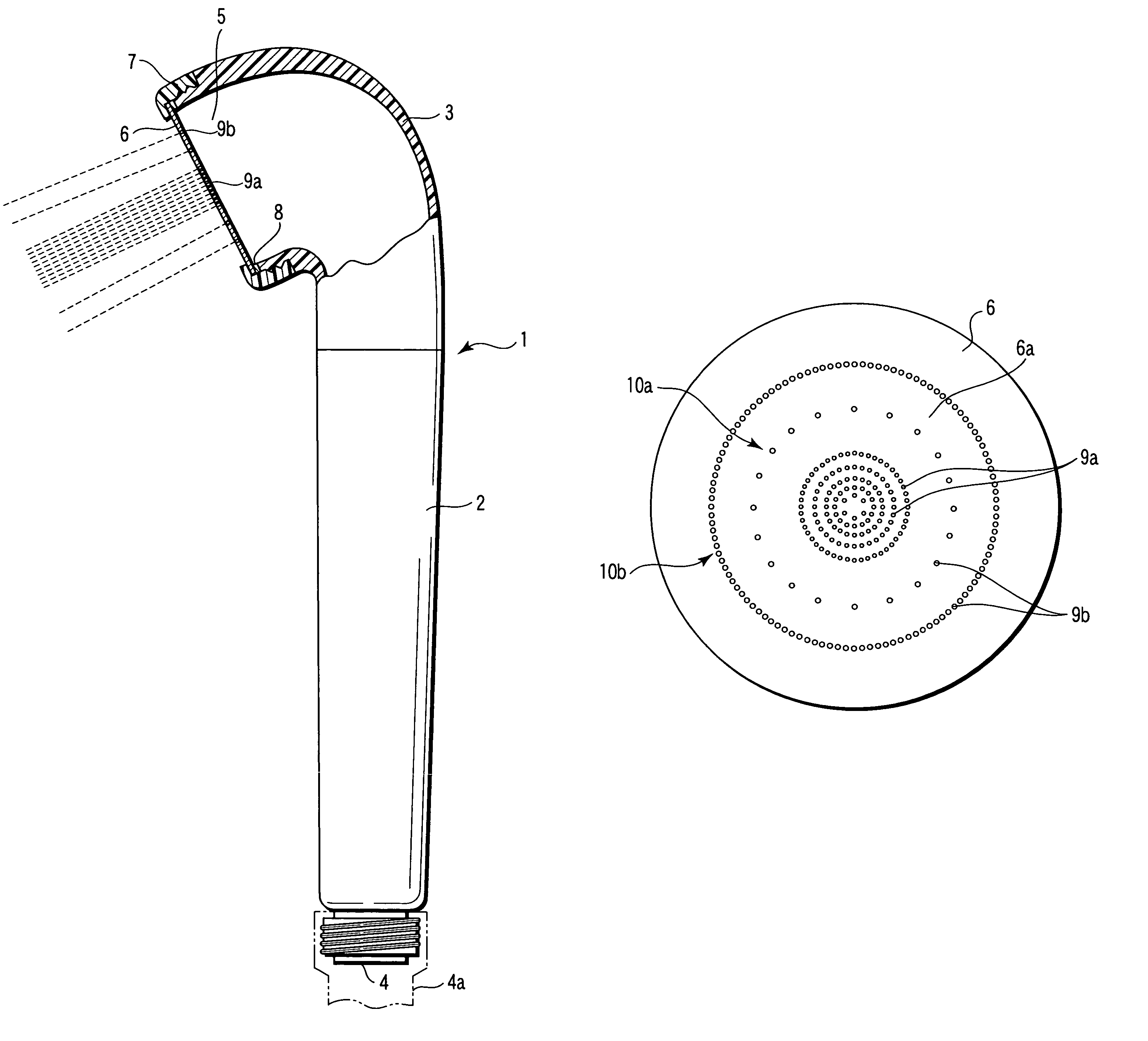
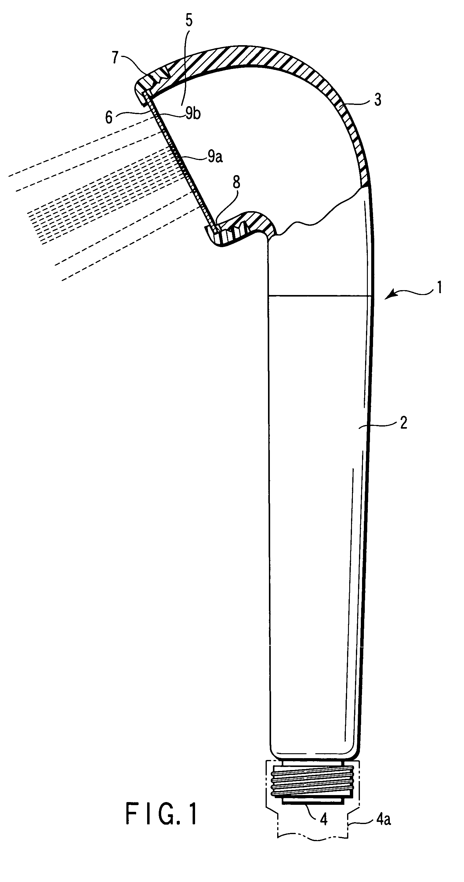
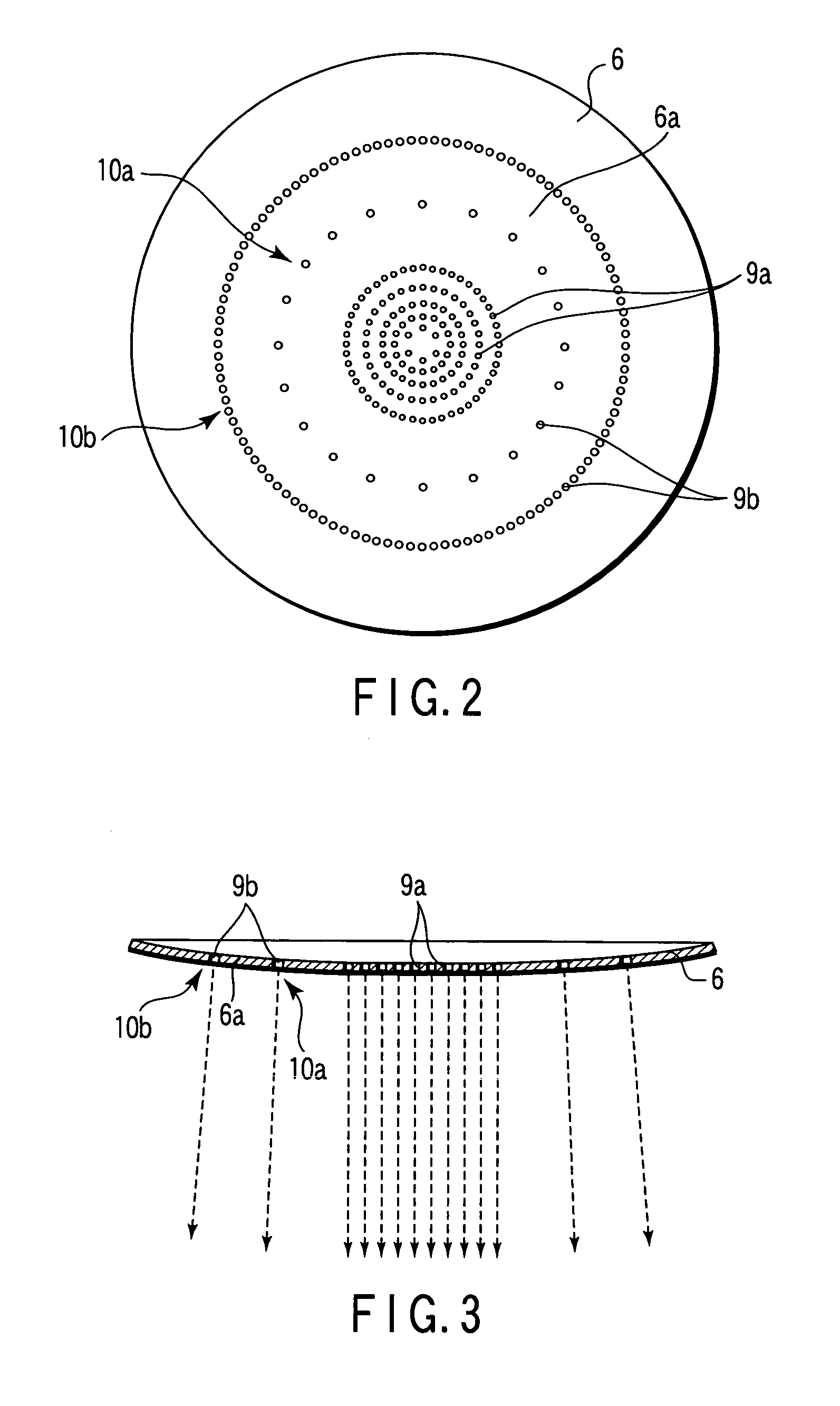
[0035]One embodiment will now be explained with reference to FIGS. 1 to 3 in which the present invention is applied to a shower head. FIG. 1 is a side view illustrating a part of a shower head in a sectional manner, FIG. 2 is a front view of a water spray plate, and FIG. 3 is a sectional view of the water spray plate.

[0036]A main body of the shower head 1 as illustrated in FIG. 1 comprises a grip portion 2 and a head portion 3. The grip portion 2 and the head portion 3 are made of synthetic resin, and are connected together through means such as screw joint or bayonet joint (not shown) in a freely attachable / detachable manner.

[0037]The grip portion 2 is of hollow cylindrical shape and includes a feed port 4 at one end thereof. The feed port 4 is connected to a shower hose 4a (only a part thereof is illustrated). The shower hose 4a is connected, as conventionally known, to a hydrant cock or a mixing cock or similar.

[0038]The head portion 3 is connected to the other end of the grip 2....


PUM


Abstract

A number of water spray holes formed on a water spray plate is not less than 130. A diameter of the respective water spray holes is not less than 0.1 mm and not more than 0.5 mm, and an entire aperture area thereof is not more than 30 mm2. With this arrangement, since the entire aperture area of the water spray holes is reduced, it is possible to achieve water-saving effects. Moreover, since the water spray holes are small and provided by a plurality of numbers, the flow of water sprayed from the respective water spray holes is large to feel some strength hitting the skin and to achieve expansion of shower water so that the sense of using the shower may be satisfied. Moreover, since a plurality of small water spray holes is formed, a larger number of minus ion can be generated.

Description

CROSS-REFERENCE TO RELATED APPLICATIONS[0001]This is a Continuation application of PCT Application No. PCT / JP03 / 01807, filed Feb. 19, 2003, which was not published under PCT Article 21(2) in English.[0002]This application is based upon and claims the benefit of priority from prior Japanese Patent Applications No. 2002-093253, filed Feb. 22, 2002; and No. 2002-099369, filed Feb. 26, 2002, the entire contents of both of which are incorporated herein by reference.BACKGROUND OF THE INVENTION[0003]1. Field of the Invention[0004]The present invention relates to a structure of a water spray plate for spraying shower water that is mounted to particularly a tip end of a shower head as one used in shower rooms, bathrooms, wash sinks or in barbershops and beauty salons.[0005]2. Description of the Related Art[0006]A shower head is generally arranged in that a water spray plate is mounted to a tip end of a main body of the shower head that is connected to a shower hose. A plurality of small wate...

Claims


Application Information

Patent Timeline
Patent Type & Authority Patents(United States)
IPC IPC(8): B05B1/14B05B9/08B05B1/18
CPCB05B1/185B05B1/18
Inventor OKUBO, TAKAYASU
Owner OKUBO TAKAYASU
Learn More