Clamping device

Active Publication Date: 2006-02-28
SMC CORP
View PDF1 Cites 9 Cited by
  • Summary
  • Abstract
  • Description
  • Claims
  • Application Information

AI Technical Summary

Benefits of technology

[0019]According to the invention, it is possible to obtain a simple clamping device by which both of the proper driving force for rotating and moving the clamping arm to the clamping position and the proper driving force for generating the final clamping force can be obtained. It is also possible to obtain a cla

Problems solved by technology

If a degree of the performance of the driving source is adapted to a rotating force of the

Method used


Image

  • Clamping device
  • Clamping device
  • Clamping device

Examples


Embodiment Construction

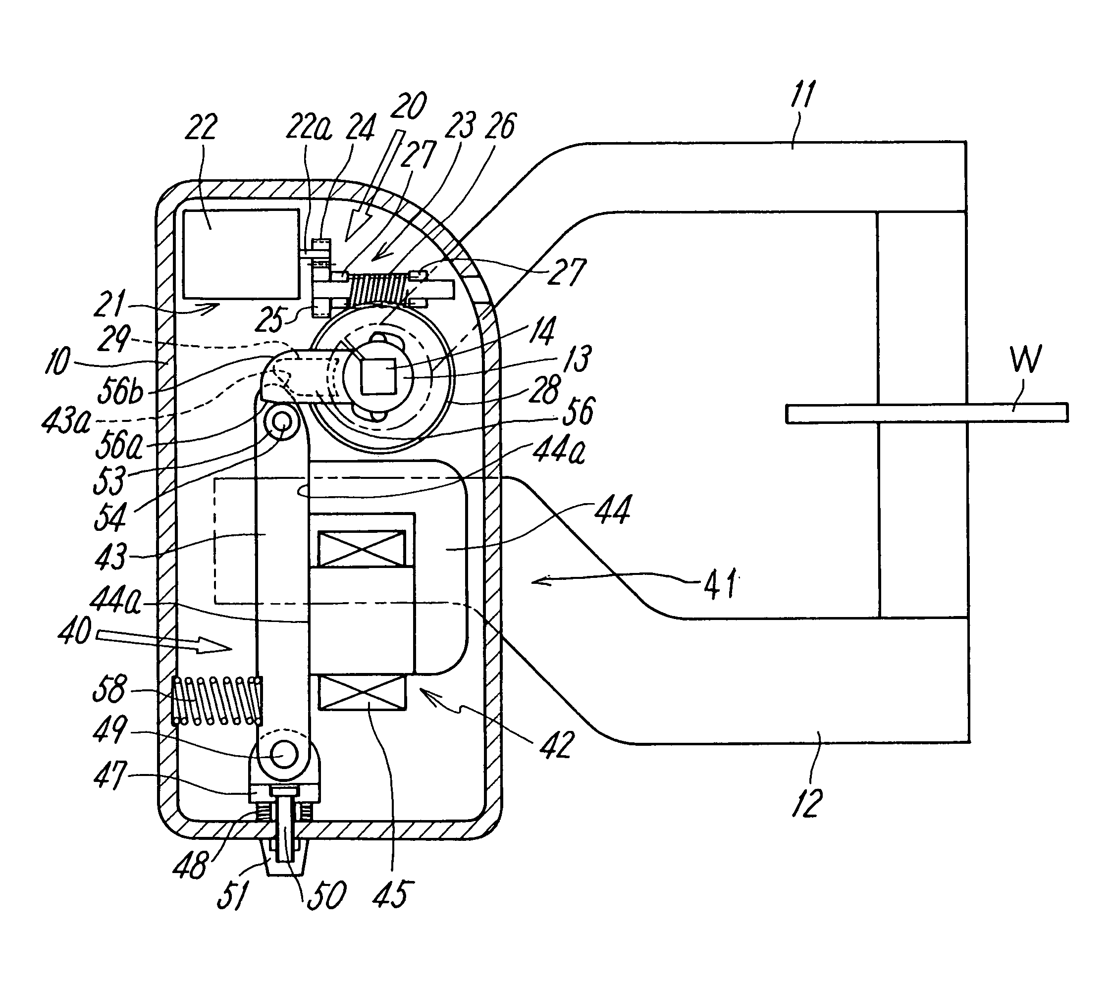
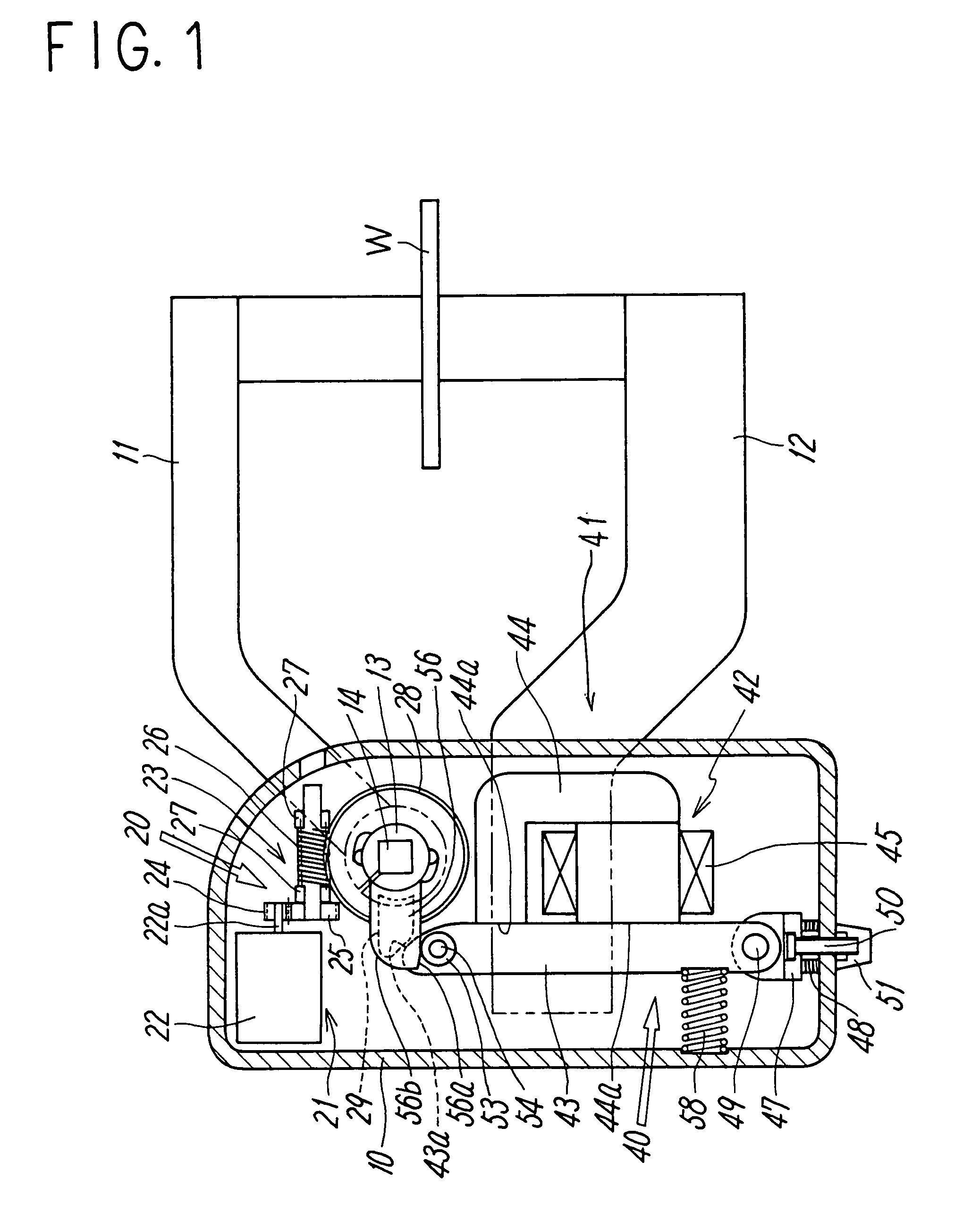
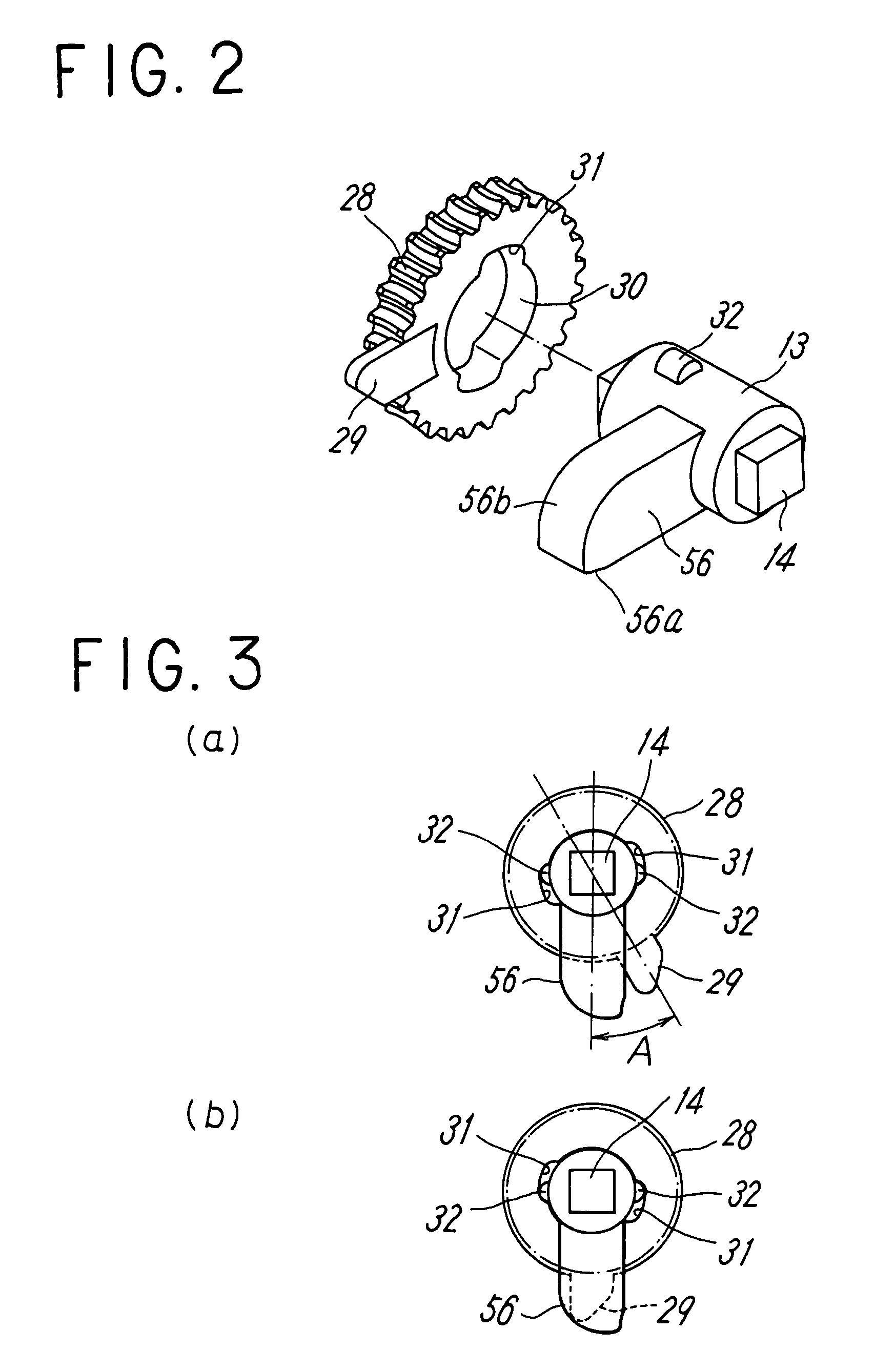
[0030]FIGS. 1 to 3 show an embodiment of an electric clamping device according to the present invention. The clamping device clamps a workpiece W between a first clamping arm 11 pivotally supported on a body 10 and a second clamping arm 12 fixed to the body 10. Components provided in the body 10 are broadly divided into an arm driving portion 20 for turning the first clamping arm 11 to a clamping position and a clamping force applying portion 40 for applying a clamping force to the first clamping arm 11 which has turned to the clamping position. The first clamping arm 11 is detachably mounted to an angular shaft portion 14 at an outer end of a rotary shaft 13 rotatably supported on the body 10.

[0031]The arm driving portion 20 has a first driving source 21 for turning the first clamping arm 11. The first driving source 21 is formed of an electric motor 22. The electric motor 22 is connected to the rotary shaft 13 of the first clamping arm 11 via a power transmission mechanism 23 and ...


PUM


Abstract

A clamping device includes a first clamping arm and a second clamping arm, an arm driving portion for displacing the first clamping arm to a clamping position and a non-clamping position, and a clamping force applying portion for applying a required clamping force to the clamping arm. The arm driving portion has a first driving source for displacing the first clamping arm and a power transmission mechanism. The clamping force applying portion has a pressing member for applying the clamping force to the first clamping arm by applying a rotating force in a clamping direction to the rotary shaft and a second driving source for displacing the pressing member from a non-operating position to an operating position for applying the clamping force.

Description

TECHNICAL FIELD[0001]The present invention relates to a clamping device for clamping a workpiece for a purpose of processing and the like.BACKGROUND ART[0002]In an automatic assembly line or the like in the automobile industry, a clamping device for clamping a workpiece for a purpose of processing is frequently used. As such a clamping device, there are already-known devices as disclosed in Japanese Patent Application Laid-open No. 2001-105332, Japanese Patent Application Laid-open No. 2001-310225, Japanese Patent Application Laid-open No. 2001-009741, and the like, for example.[0003]In this clamping device, a first clamping arm is rotated and moved to a clamping position and then a large clamping force for clamping is generated. In this case, the first clamping arm is substantially at no load while moving to the clamping position and therefore a large driving force is not required from a driving source. On the other hand, in a stage of generating the clamping force, the large drivi...

Claims


Application Information

Patent Timeline
IPC IPC(8): B25B1/06B23Q3/06B25B5/08
CPCB25B5/08
Inventor SATO, TOSHIOTADANO, AKIRA
Owner SMC CORP
Why Eureka
Try Eureka