
Interior rearview mirror system with compass

a compass and rearview mirror technology, applied in the field of interior rearview mirror assemblies, can solve the problems of high cost of compass mirror assemblies, inability to adapt to use with double ball or double pivot mirror assemblies, and special tools, etc., and achieve the effect of low cost, convenient installation and low cos

Inactive Publication Date: 2006-02-28
DONNELLY CORP
View PDF43 Cites 658 Cited by
  • Summary
  • Abstract
  • Description
  • Claims
  • Application Information

AI Technical Summary

Benefits of technology

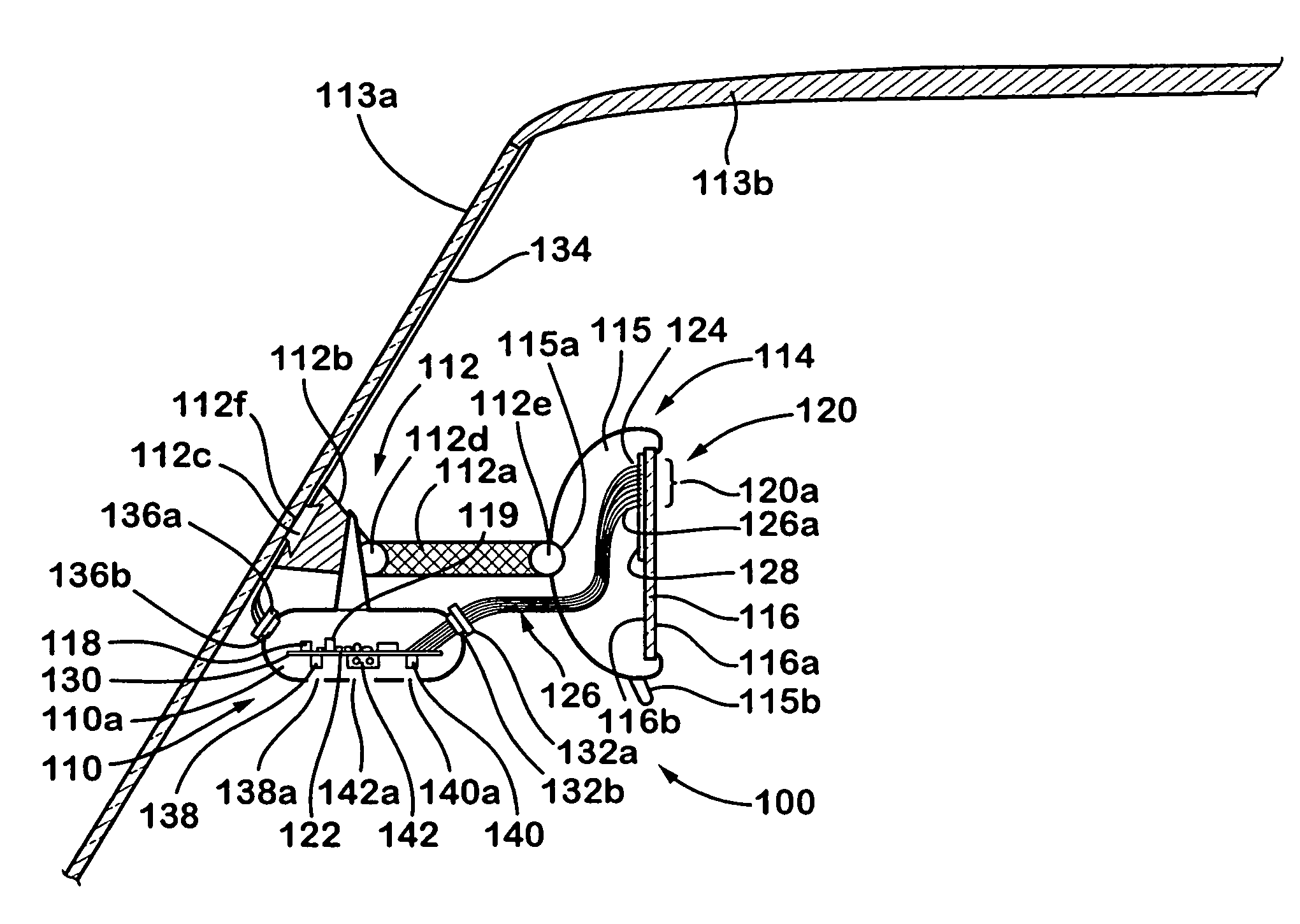
[0010]The present invention is intended to provide a low cost interior rearview mirror system which includes a compass system having a display which indicates the general direction in which the vehicle is traveling. The entire compass system, including the compass sensor, may be included on a single printed circuit board positioned at or secured to a back surface of the mirror reflective element, which may be a prismatic mirror reflective element (for low cost implementation), such that the compass / mirror system may be readily installed in the casing of the mirror assembly, and may be installed simultaneously (and with minimal if any additional labor involved) as the reflective element is included in the mirror casing, such as snapped into or otherwise secured to / within the mirror casing.

Problems solved by technology

Such compass mirror assemblies can be costly and often involve special tooling and complicated adaptation of the mirror assembly itself and the casing of the mirror assembly.
Also, such compass systems as described in the patents referenced above are not readily adapted for use with double ball or double pivot mirror assemblies.
However, the display, typically a VF display, has its own logic, circuitry, drivers and / or photosensor input (for adjustment of the display in response to ambient lighting in the vehicle), which may not readily communicate with the circuitry output of the compass pod.
This can result in an expensive compass add-on device, since it may be costly to encode and decode the signals from the compass circuitry.
While such modules may work well in many applications, such incorporation of the information display of compass direction / heading in the module has disadvantages, including the need to assure readability of the display by the driver of the vehicle.
Several potential solutions have been proposed that can involve costly and complicated additions to the vehicle.

Method used


Image

  • Interior rearview mirror system with compass
  • Interior rearview mirror system with compass
  • Interior rearview mirror system with compass

Examples


Embodiment Construction

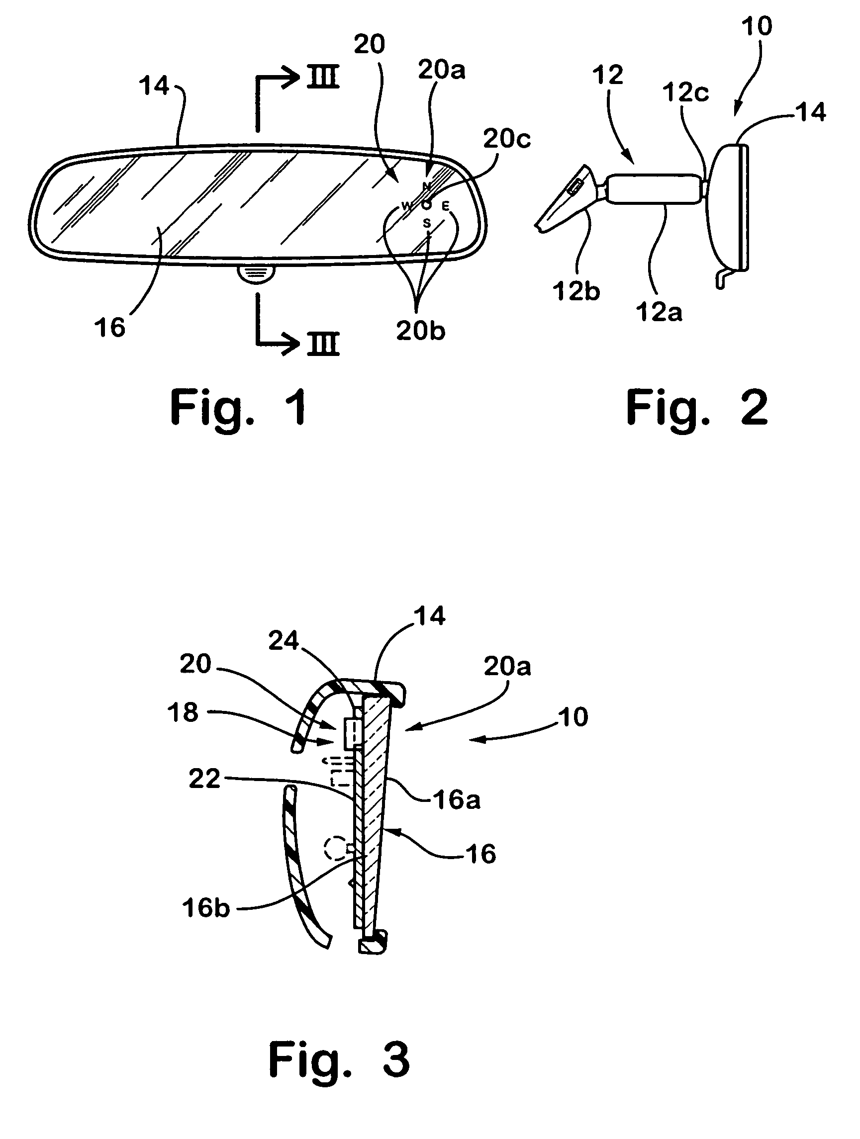
[0052]Referring now to the drawings and the illustrative embodiments depicted therein, a compassized prismatic interior rearview mirror assembly or system 10 includes a double pivot or double ball mounting arrangement 12 for pivotally or adjustably mounting a casing 14 and prismatic reflective element 16 of mirror assembly 10 relative to an interior portion of a vehicle, such as to an interior surface of a windshield (not shown) of a vehicle (FIGS. 1–3) or the like. The mirror assembly 10 includes a compass system 18, which includes a compass sensor (not shown) and a display 20 for providing a display or indication of the directional heading of the vehicle at the reflective element 16 of the mirror.

[0053]As shown in FIG. 2, the double ball or double pivot mirror mounting arrangement 12 includes a mounting arm 12a which is pivotally mounted at opposite ends to a mirror mount 12b (mounted at the windshield or headliner of the vehicle, such as at a mounting button at the interior surfa...


PUM


Abstract

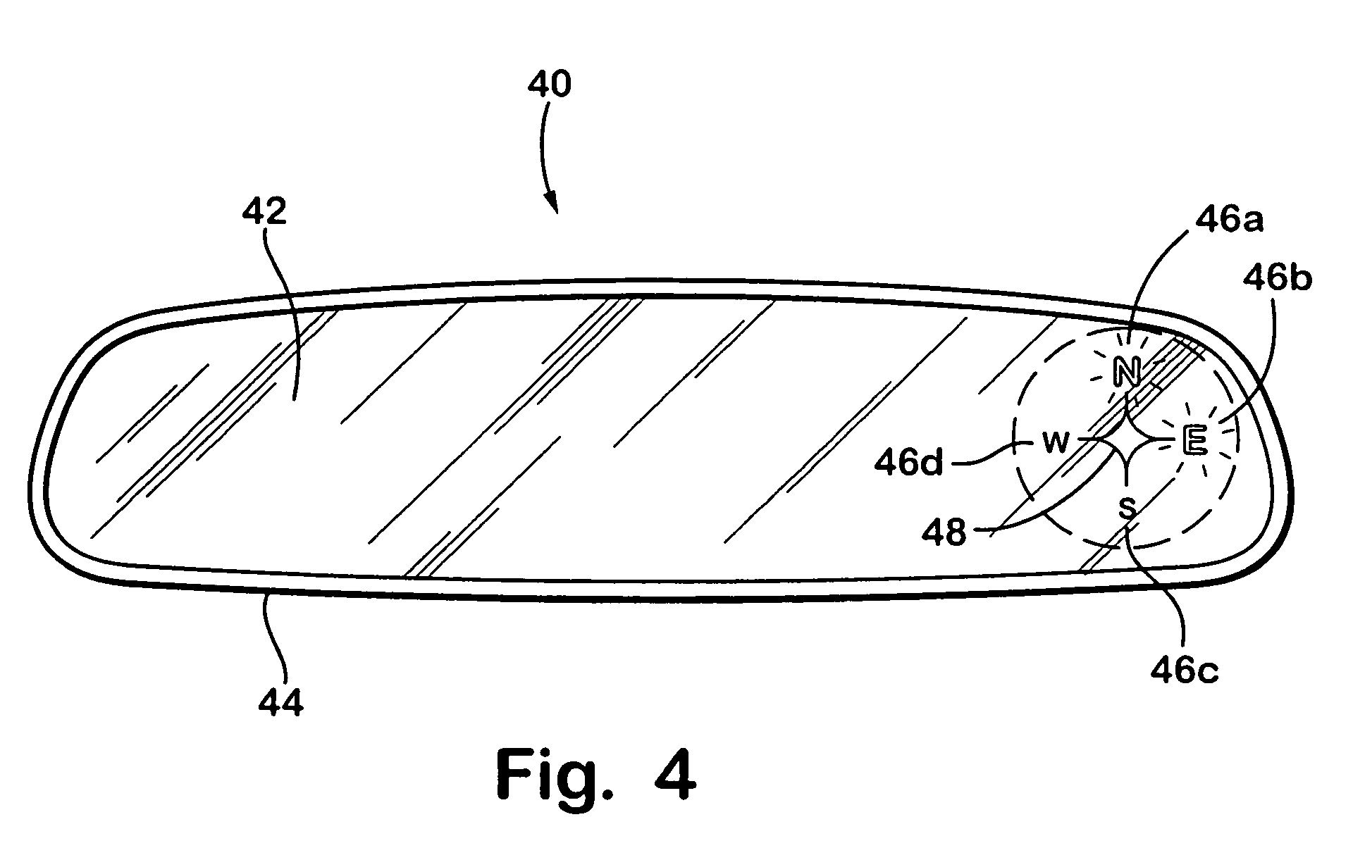
An interior rearview mirror system includes a compass system and a display. The compass system is operable to display information indicative of a directional heading of the vehicle to a driver of the vehicle. The display comprises a plurality of ports formed in a reflective coating of a mirror reflective element and includes illumination sources positioned behind and generally aligned with corresponding ones of the ports. Each of the illumination sources may be energized to project illumination through a respective one of the ports such that the ports are backlit by the respective illumination sources, in order to convey the directional information to the driver of the vehicle. The system may include a microprocessor operable to control each illumination source via a respective wire connected between the microprocessor and each illumination source. The compass system may utilize a global positioning system for vehicle direction determination.

Description

CROSS REFERENCE TO RELATED APPLICATIONS[0001]The present application claims the benefit of U.S. provisional applications, Ser. No. 60 / 420,010, filed Oct. 21, 2002; Ser. No. 60 / 398,240, filed Jul. 24, 2002; and Ser. No. 60 / 386,373, filed Jun. 6, 2002, which are all hereby incorporated herein by reference in their entireties.FIELD OF THE INVENTION[0002]The present invention relates generally to interior rearview mirror assemblies for vehicles and, more particularly, to an interior rearview mirror assembly which includes a compass system.BACKGROUND OF THE INVENTION[0003]Interior rearview mirror assemblies which include a directional or compass display are known, such as the types disclosed in U.S. Pat. No. 5,802,727, which is hereby incorporated herein by reference. Typically, such mirror assemblies include a compass sensor, such as a magnetoresistive sensor, a magnetocapacitive sensor, a magnetoinductive sensor, or a flux gate sensor or the like, which is fixedly attached to the mirro...

Claims


Application Information

Patent Timeline
IPC IPC(8): G02B7/182B60R1/12
CPCB60R1/12B60R2001/1215
Inventor WELLER, ANDREW D.BLANK, RODNEY K.SCHIERBEEK, KENNETH L.SCHOFIELD, KENNETHLYNAM, NIALL R.COOPRIDER, TROY O.
Owner DONNELLY CORP
Learn More