Outrigger lifting device for fuel tankers

a technology of lifting device and fuel tanker, which is applied in the direction of load accommodation, transportation items, and well accessories, etc., can solve the problems of large amount of liquid hydrocarbons required for the transfer of large amounts, easy destruction or sabotaging, and lost time spent filling the tanker

Inactive Publication Date: 2006-02-28
ARMY UNITED STATES GOVERNMENT AS REPRESENTED BY THE SEC OF THE
View PDF8 Cites 10 Cited by
  • Summary
  • Abstract
  • Description
  • Claims
  • Application Information

AI Technical Summary

Benefits of technology

[0006]The structure of the present invention provides an improved unloading sling and attachment configuration that will allows a fully loaded fuel tanker to be safely lifted as a unit. The unloading structure of this invention has first and second transverse members located beneath and permanently attached to longitudinal rails located on the underside of the reservoir portion of the tanker. The first and second transverse members have an attachment means located on each end. The attachment means are moveable coaxially from a first inboard, shipping position to a second outboard lifting position. The attachment means in the second position extend to a point beyond the tanker for easy attachment of lifting cables. The attachment means have an eye or similar attachment means that allow the transverse members to be attached to the free ends of a four-cable cargo sling structure. The cables are in turn attached at their other end to a single lift ring that can be engaged by a crane hook for loading and unloading the tanker. The cables will have a spreader bar located at a point between the lift ring and the cable end to maintain the cables in a spaced configuration approximating the width of the tanker.

Problems solved by technology

Obviously the time spent filling the tanker is lost time to the main mission.
Further while the tanker is being filled it represents a vulnerable, stationary target for a substantial period of time making it easily destroyed or sabotaged.
A third problem with the present procedure is it requires the transfer of large amounts of liquid hydrocarbons.
This creates risk of spillage, hydrocarbon emissions, and fire.
This procedure when using belly bands or nets creates its own hazards since the loaded tankers are considerably heavier than the empty tanker and if the sling system fails the release of flammable, polluting hydrocarbons would be both large and virtually instantaneous.

Method used


Image

  • Outrigger lifting device for fuel tankers
  • Outrigger lifting device for fuel tankers
  • Outrigger lifting device for fuel tankers

Examples


Embodiment Construction

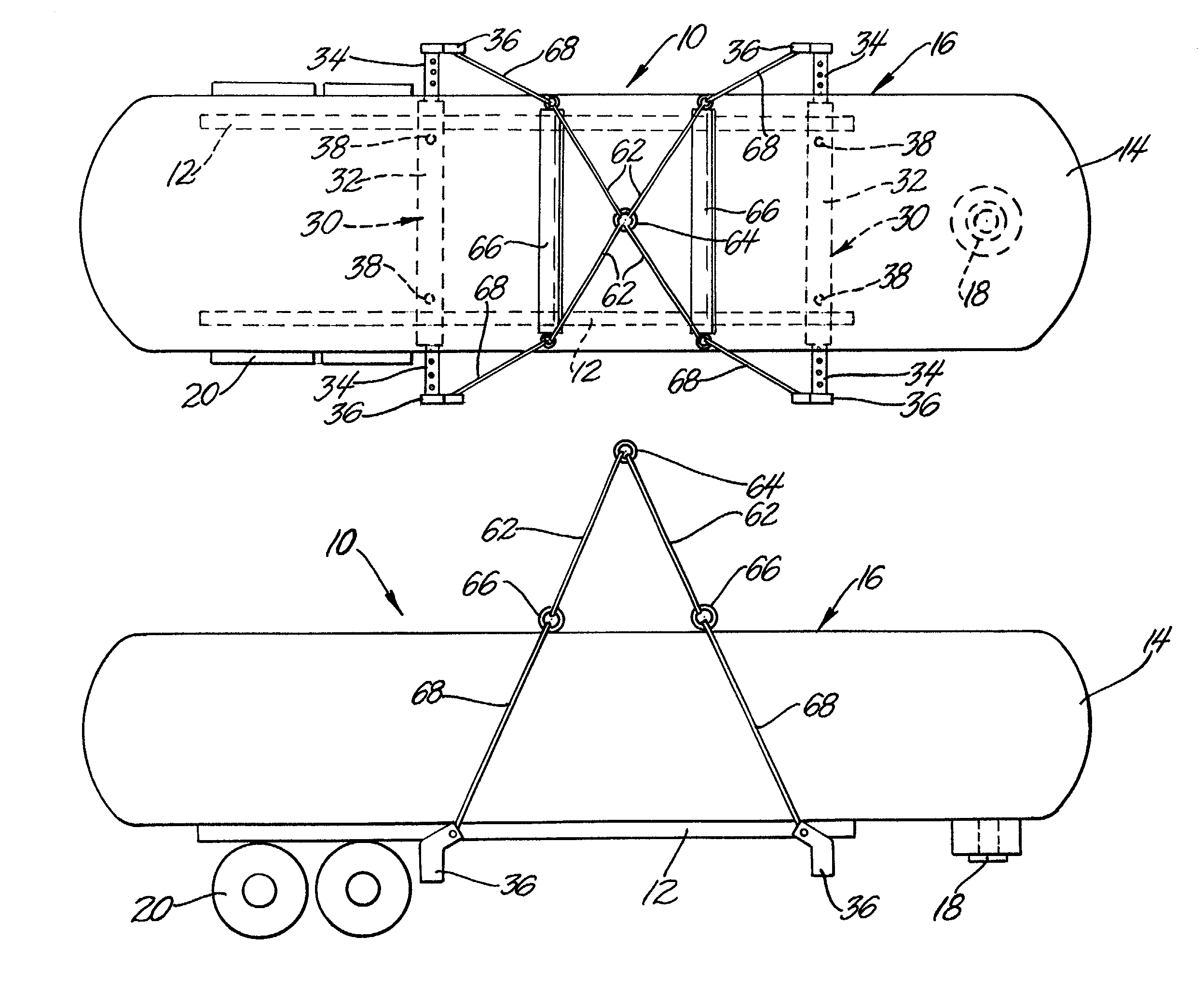
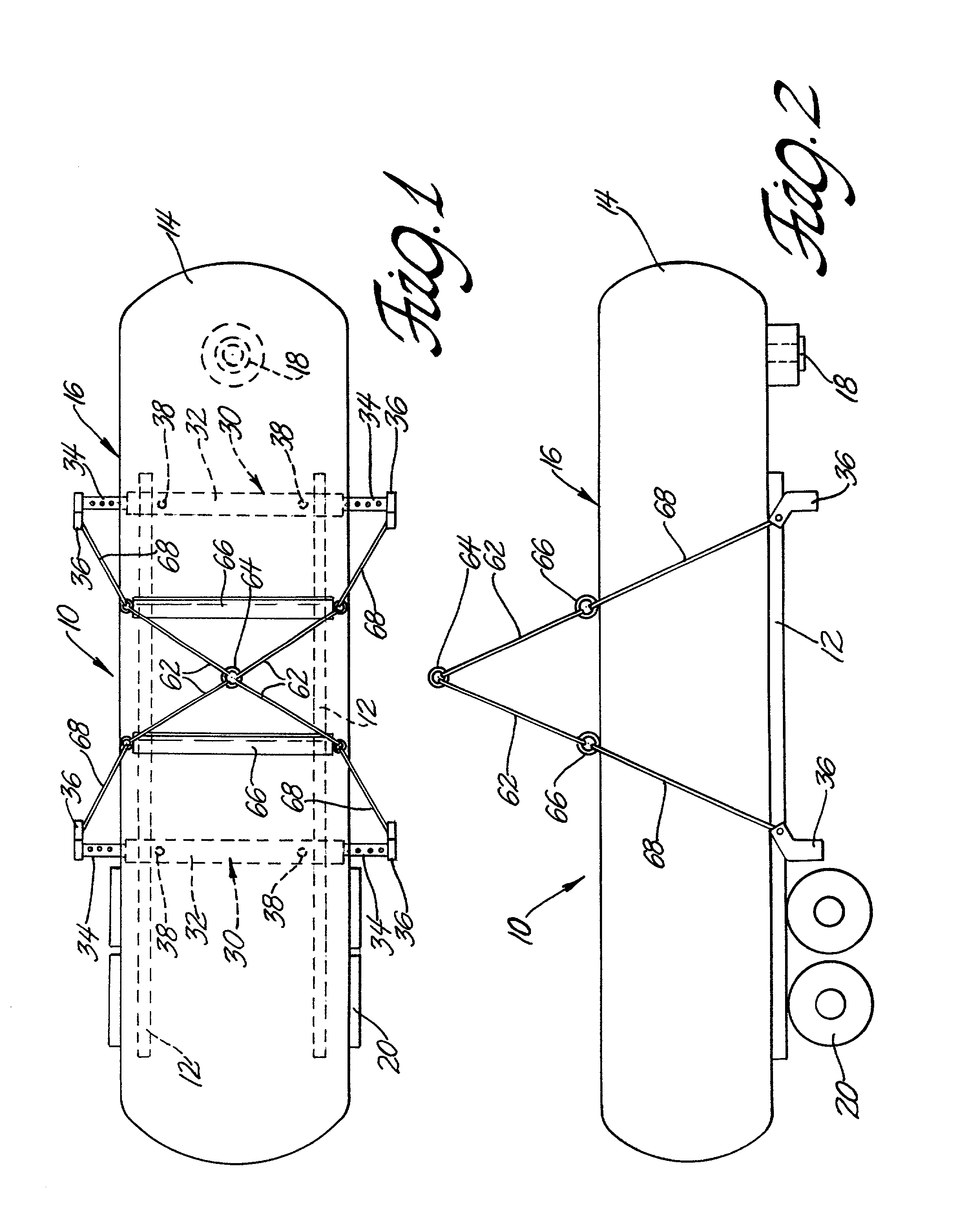
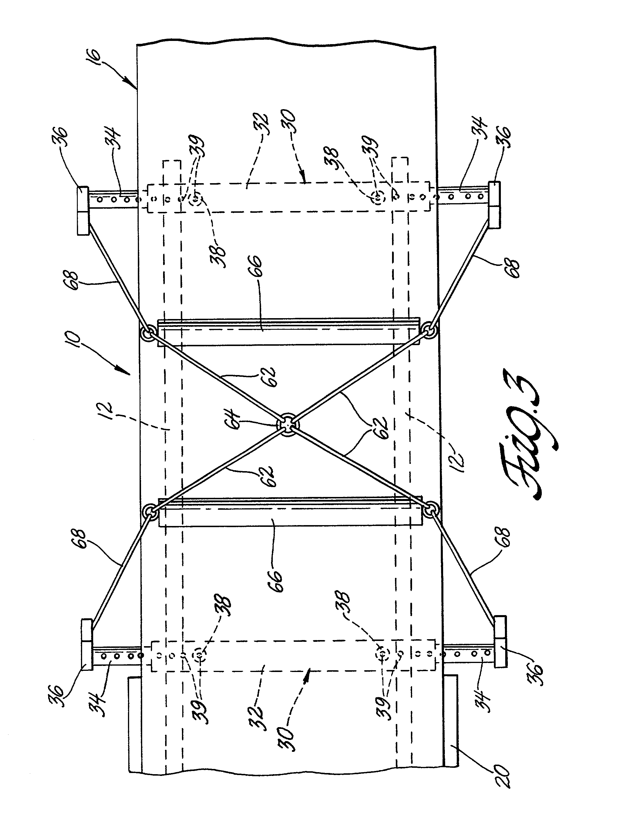
[0011]Referring to the accompanying drawings in which like numerals refer to like parts, FIGS. 1 & 2 shows a load handling structure according to this invention integrated with a fuel tanker. The load handling structure is designated generally 10, and is permanently attached to a pair of supporting members or under carriage longitudinal beams 12 that form the primary supporting structure of a fuel reservoir 14. The fuel reservoir 14 contemplated by this invention is on the order of 5,000 gallons. The longitudinal beams 12 are attached to the fuel reservoir 14 so as to traverse its length. The fuel tanker and ancillary equipment 16 has a kingpin structure 18 attached at one end. The kingpin structure 18 is of normal design and construction for connecting the tanker 16 to a standard truck-tractor, not shown, for transport. A set of wheels 20, shown as a standard dual tire truck configuration, is mounted on the end of the tanker 16 opposite the king pin structure 18 to provide rolling ...


PUM


Abstract

A load handling mechanism for use with loaded tankers has two transverse attachment members associated with longitudinal beams supporting the tank structure. Cables and associated spreader bars are attached to the transverse attachment members to provide a single lift point loading means for the tanker allowing loaded tankers to be easily loaded and unloaded in to transport means such as ships.

Description

GOVERNMENT INTEREST[0001]The invention described here may be made, used and licensed by and for governmental purposes without paying me any royalty.BACKGROUND OF THE INVENTION[0002]In one aspect this invention relates to cargo handling devices. More particularly this invention relates to sling structures useful in loading and unloading ground vehicle fuel tankers from ships.[0003]As part of supplying military deployments it is necessary to provide fuel in large quantities to various locations. The supply chain depends on large, 5,000-gallon, tankers moved using large truck-tractors as the primary means of distributing fuel. The general procedure is to move the empty tankers in ships and unload the tanker at a destination port using a belly band or net configuration. The empty tanker is then filled with fuel and is ready for further transport. The entire unloading and filling operation requires approximately six hours per tanker from start to finish.[0004]Obviously the time spent fil...

Claims


Application Information

Patent Timeline
Patent Type & Authority Patents(United States)
IPC IPC(8): B60P7/08B60P3/00B60P3/22B65D90/00B66C1/10
CPCB60P3/2245B66C1/10B65D90/0033
Inventor ALAWEIH, ADAM
Owner ARMY UNITED STATES GOVERNMENT AS REPRESENTED BY THE SEC OF THE
Why Eureka
Try Eureka