Load cell including angular and lateral decoupling

Inactive Publication Date: 2006-02-28
INTELLIGENT MECHANTRONIC SYST INC
View PDF21 Cites 23 Cited by
  • Summary
  • Abstract
  • Description
  • Claims
  • Application Information

AI Technical Summary

Benefits of technology

[0009]The noticeable benefits of this solution, after a comparison with the prior solution, are as follows: translates 100% of the axial component of force to the force sensitive unit; protects delicate force sensitive unit from applied lateral force, torque, mutual angular and lat

Problems solved by technology

The shock absorbing bushing is placed in this gap so even if lateral shift or angular misalignment exists, and corresponding loads are applied, the stud has no sufficient friction; therefore allowing the inevitable and necessary m

Method used


Image

  • Load cell including angular and lateral decoupling
  • Load cell including angular and lateral decoupling
  • Load cell including angular and lateral decoupling

Examples


Embodiment Construction

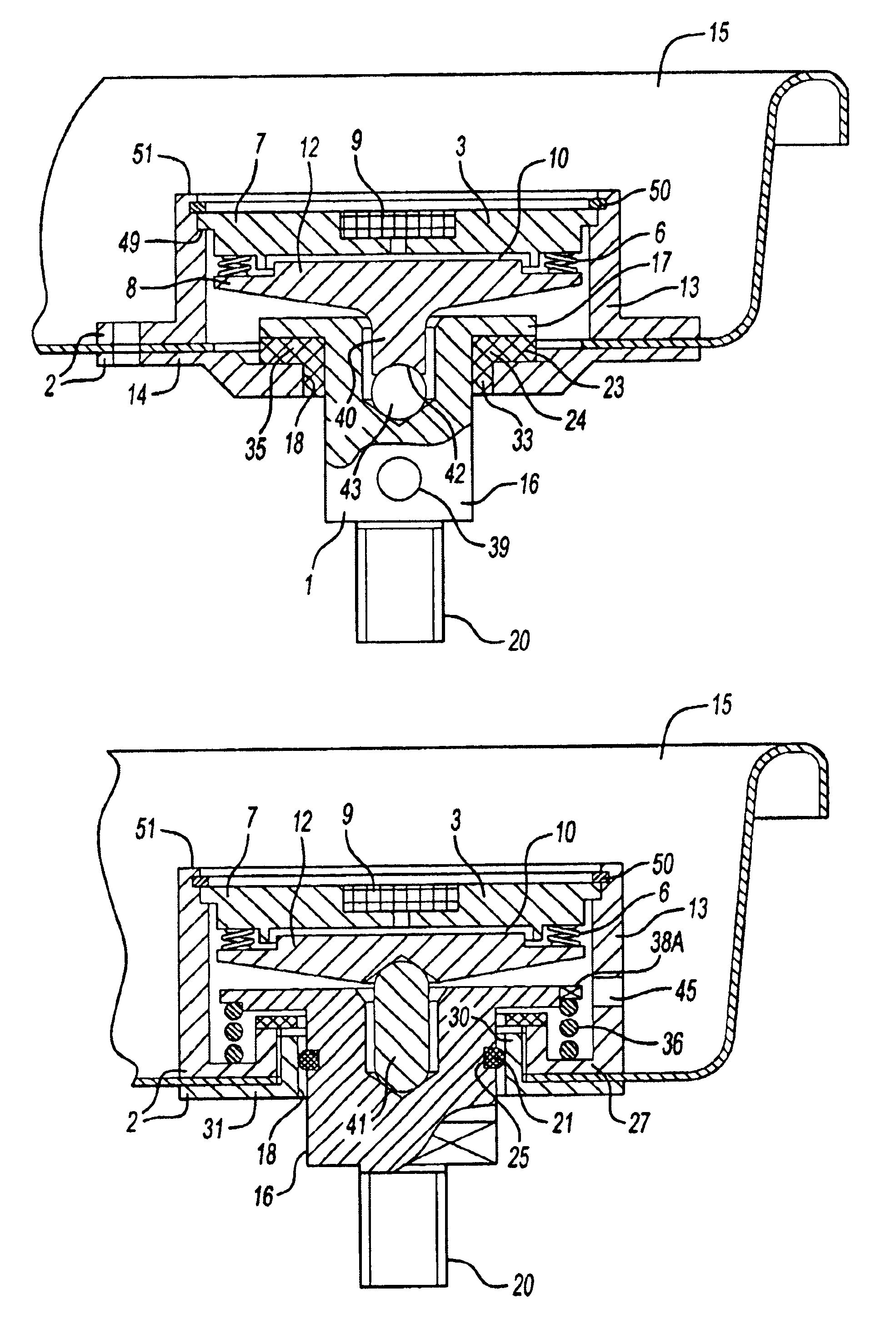
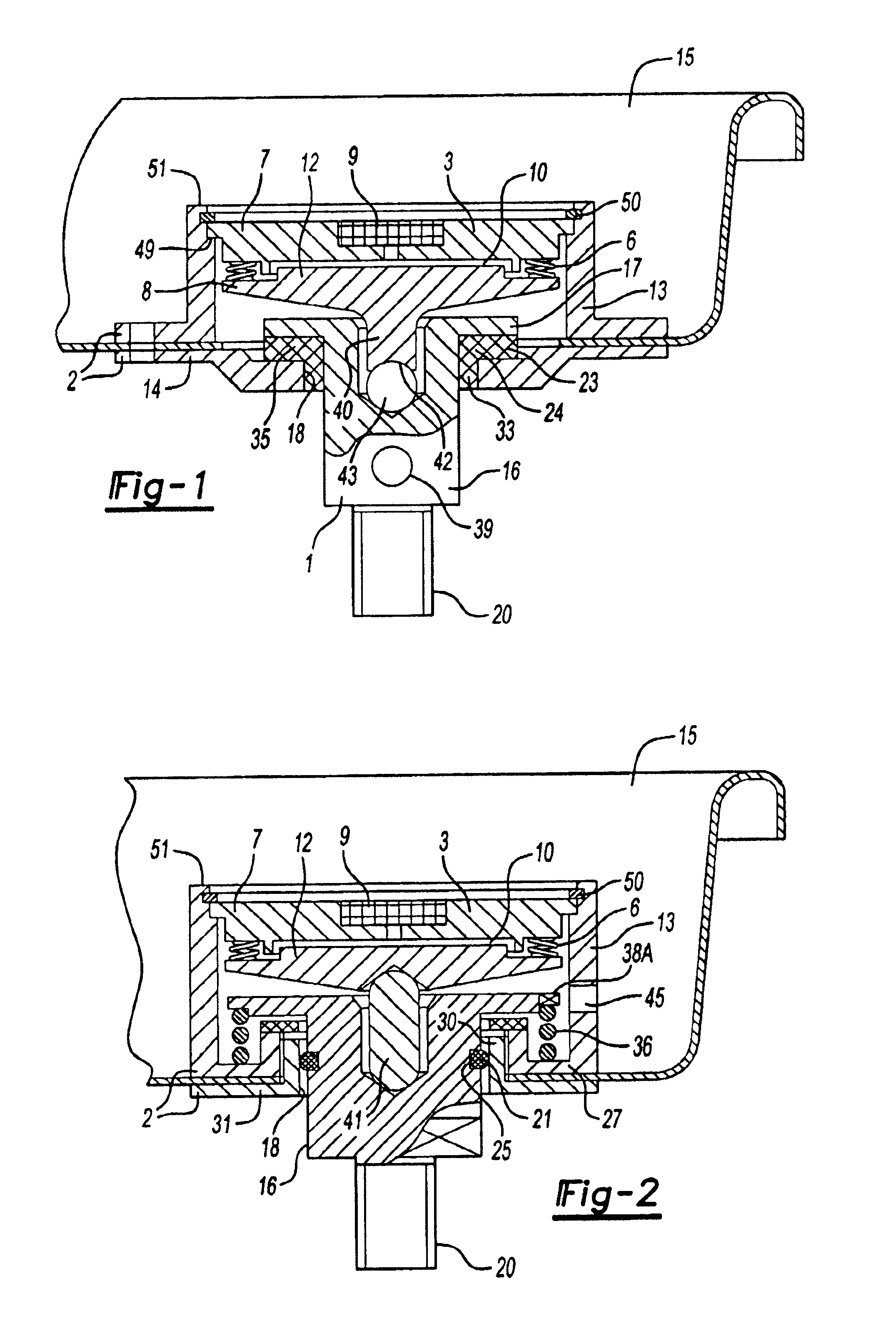
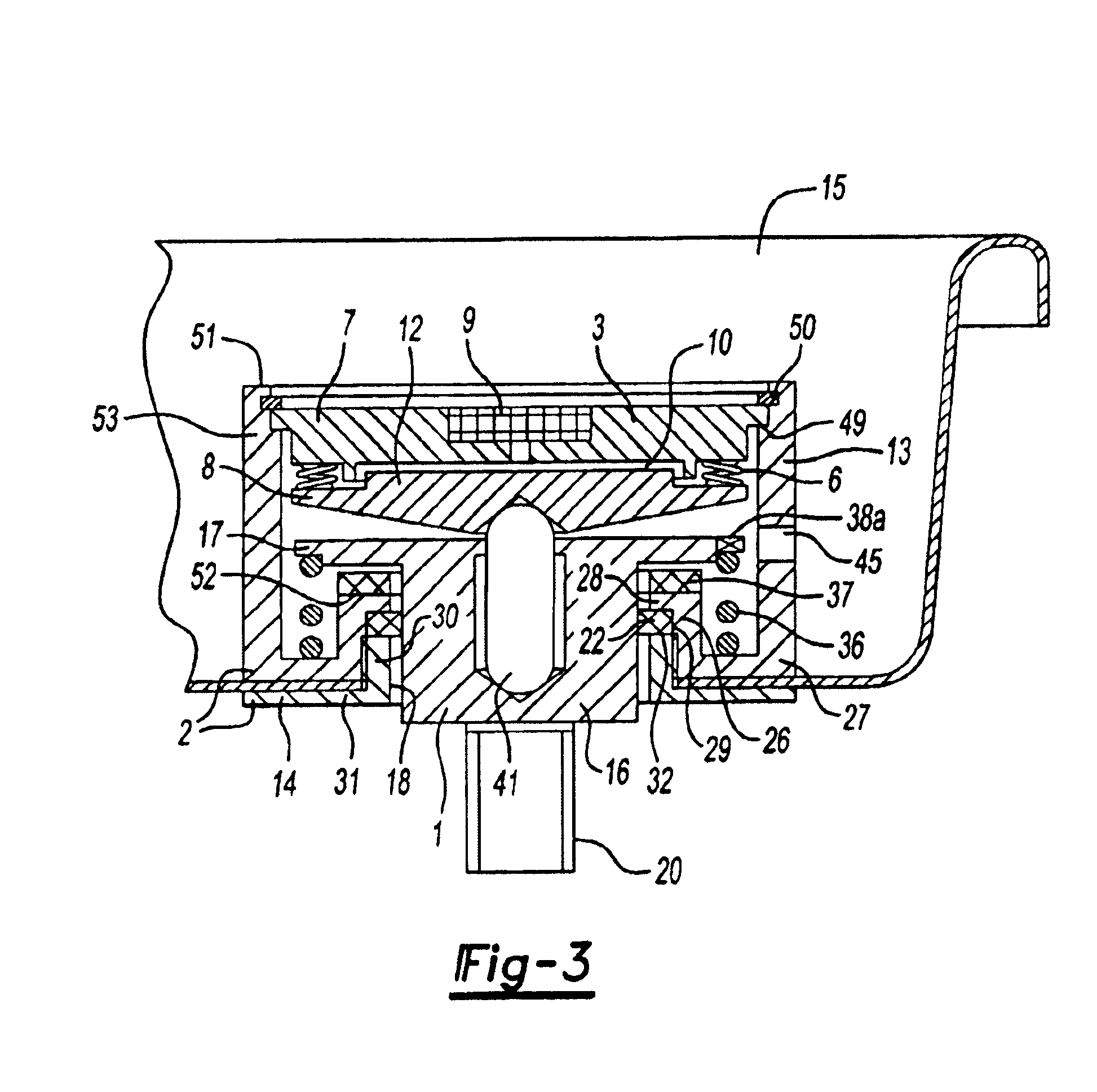
[0021]The load cell of the present invention generally includes coaxially oriented lower and upper rigid elements, mount 1 and upper housing 2, that can be attached to the corresponding bottom and upper structural parts of the seat and which construct the contours of the whole load cell (FIGS. 1-3). It should be understood that words ‘upper’ and ‘bottom’ are used to simplify the description of the invention. The described load cell can be installed in any position.

[0022]The force sensitive unit is shown in several variants: in FIGS. 1, 2, 3 the hydraulic kind of force sensitive unit 3 is made as a bellows 6 with upper flange 7, bottom flange 8, pressure sensing device 9 on it and filled with a liquid 10. At least one from two flanges 7 and 8 has a boss 12 on its inner surface as high as it is needed for minimizing of the volume of the liquid 10 with saving of warranted gap between flanges.

[0023]In FIGS. 4-7a, 8, 10-13 this force sensitive unit is shown as a disk spring 4, loaded in ...


PUM


Abstract

A load cell includes a first element, a second element and a sensor measuring force between the first and second elements along a first axis. In some embodiments, lateral and angular decoupling is provided by the provision of a convex surface between the first and second elements. The convex surface is slidable relative to at least one of the first and second elements in a first direction perpendicular to the first axis.

Description

[0001]This application claims priority to U.S. Provisional Applications Ser. Nos. 60 / 417,562 filed Oct. 10, 2002 and 60 / 358,640 filed Feb. 21, 2002.BACKGROUND OF THE INVENTION[0002]The present inventions relates generally to a load cell and more particularly to a load cell for determining the weight and position of an occupant of a vehicle seat.[0003]Generally, it is often desirable to determine the weight and position of an occupant of a seat in a vehicle passenger compartment. For example, based upon the weight of the occupant and the position of the occupant on the seat, an active safety restraint system may determine whether or not to deploy or may determine the amount of force with which to deploy. Applicant has determined that one way of achieving this is by using a plurality of load cells mounted beneath the vehicle seat. However, to get an accurate determination of weight and position, lateral and angular forces on the vehicle seat should be decoupled from the measurement.[0...

Claims


Application Information

Patent Timeline
IPC IPC(8): G01G23/14G01G5/04G01G19/12B60N2/00B60N2/90B60R21/01B60R21/015G01G19/414G01G19/52G01L1/22G01L1/26
CPCB60N2/002B60R21/01516G01G19/4142G01G21/184
Inventor AXAKOV, DMITRI L.NASSONOV, ALEXANDER M.BASIR, OTMAN A.KARRAY, FAKHREDDINCKRIVTSOV, SERGEY
Owner INTELLIGENT MECHANTRONIC SYST INC
Why Eureka
Try Eureka