Estimating a writer/reader gap in a disk drive by measuring write/read times relative to a sync mark

a technology of write/reader gap and disk drive, which is applied in the field of disk drives, can solve the problems of timing errors, reducing format efficiency, and writing/reading gap

a technology of write/reader gap and disk drive, which is applied in the field of disk drives, can solve the problems of timing errors, reducing format efficiency, and writing/reading gap

US7006316B1Active Publication Date: 2006-02-28WESTERN DIGITAL TECH INC

Image

  • Estimating a writer/reader gap in a disk drive by measuring write/read times relative to a sync mark
  • Estimating a writer/reader gap in a disk drive by measuring write/read times relative to a sync mark
  • Estimating a writer/reader gap in a disk drive by measuring write/read times relative to a sync mark

Examples


Embodiment Construction

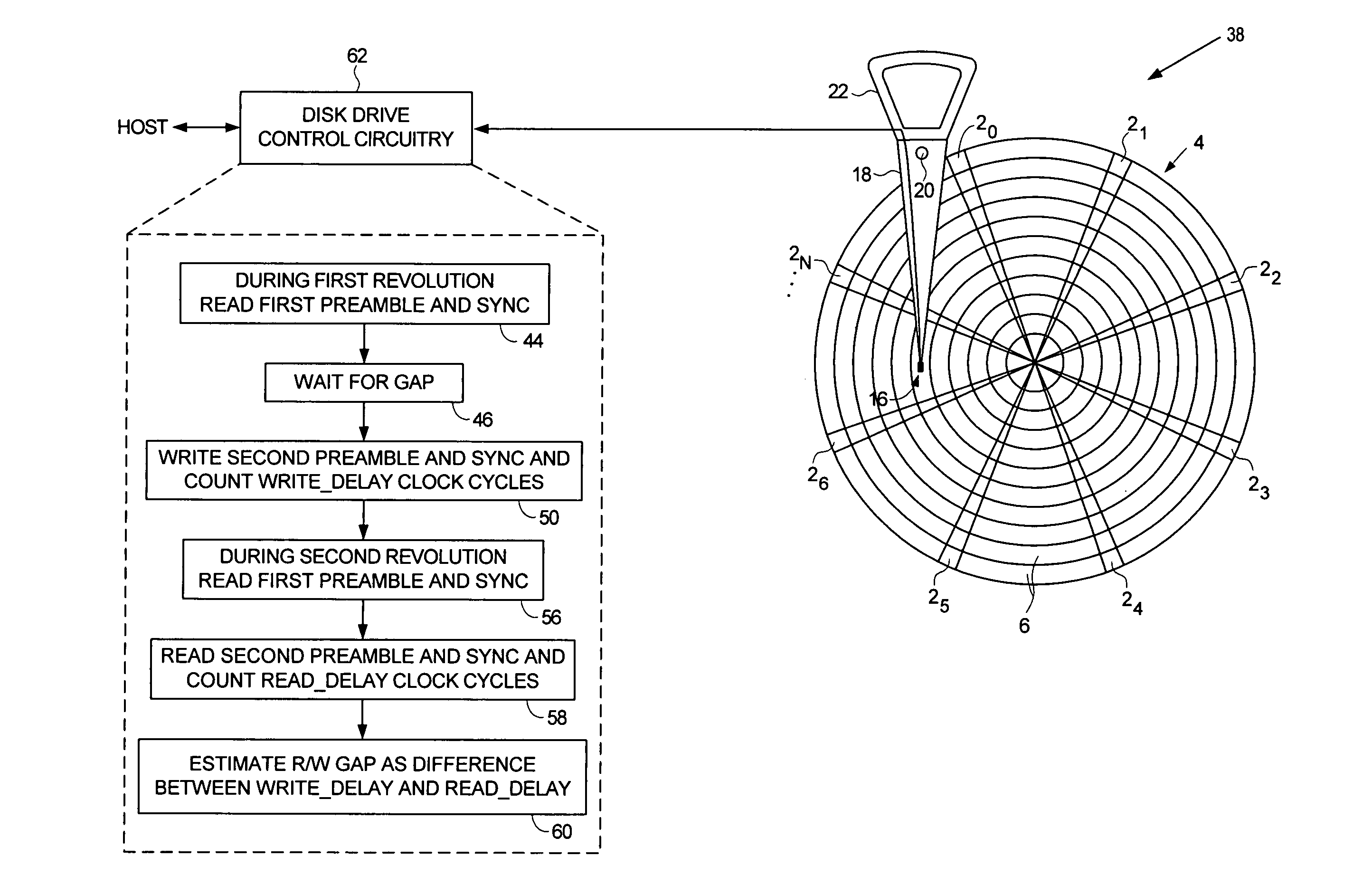
[0029]FIGS. 4A–4C illustrate an embodiment of the present invention for estimating a writer / reader gap 28 in a disk drive 38. The disk drive 38 comprises a disk 4 having a first preamble 40 and a first sync mark 42 (FIG. 4C), and a head 16 actuated over the disk 4, wherein the head 16 comprises a writer 24 separated from a reader 26 by the writer / reader gap 28. Referring to FIG. 4B, a write delay is measured during a first revolution of the disk 4. At step 44, the first preamble 40 is read to synchronize cycling of a clock, and the first sync mark 42 is detected. At step 46, a delay of a predetermined number of the clock cycles creates a gap 48 after the first sync mark 42 (FIG. 4C). At step 50, a second preamble 52 and a second sync mark 54 are written on the disk 4, and a number of the clock cycles are counted relative to when the first sync mark 42 is detected and when the second sync mark 54 is written. During a second revolution of the disk 4 a read delay is measured. At step 5...


PUM

PropertyMeasurementUnit
magnetic fluxaaaaaaaaaa
lengthaaaaaaaaaa
inner diameteraaaaaaaaaa

Abstract

A method of estimating a writer / reader gap in a disk drive is disclosed. During a first revolution of the disk, a clock is synchronized to a first preamble and used to measure a write delay to write a second sync mark to the disk relative to a first sync mark. During a second revolution of the disk, the clock is again synchronized to the first preamble and used to measure a read delay required to detect the second sync mark relative to the first sync mark. The writer / reader gap is then estimated in response to the measured write delay and the measured read delay, for example, by computing a difference between the measured write delay and the measured read delay.

Description

BACKGROUND OF THE INVENTION[0001]1. Field of the Invention[0002]The present invention relates to disk drives for computer systems. More particularly, the present invention relates to a disk drive measuring a writer / reader gap in a disk drive by measuring write / read times relative to a sync mark.[0003]2. Description of the Prior Art[0004]When manufacturing a disk drive, servo sectors 20–2N are written to a disk 4 which define a plurality of radially-spaced, concentric data tracks 6 as shown in the prior art disk format of FIG. 1. Each data track 6 is partitioned into a plurality of data sectors wherein the servo sectors 20–2N are considered “embedded” in the data sectors. Each servo sector (e.g., servo sector 24) comprises a preamble 8 for synchronizing gain control and timing recovery, a sync mark 10 for synchronizing to a data field 12 comprising coarse head positioning information such as a track number, and servo bursts 14 which provide fine head positioning information. The coar...

Claims


Application Information

Patent Timeline
28 Feb 2006
Publication
US7006316B1
IPC
G11B5/09
CPC
G11B5/455; G11B20/10; G11B5/59633; G11B5/012; G11B2005/0013; G11B2005/001
Inventors
SARGENTI, JR., WILLIAM A.; BUI, KHOA XUAN