Magnetic tape head assembly with laterally moveable central section

a technology of magnetic tape and central section, which is applied in the direction of maintaining head carrier alignment, manufacturing head surface, instruments, etc., can solve the problems of performance errors, lateral movement of the head may undetectedly “drag” the tape in a lateral fashion, performance degradation

Inactive Publication Date: 2006-02-28
IMATION
View PDF11 Cites 38 Cited by
  • Summary
  • Abstract
  • Description
  • Claims
  • Application Information

AI Technical Summary

Problems solved by technology

This air bearing can cause hydrodynamic lift of the tape relative to the magnetic head, leading to performance deterioration.
Unfortunately, due to the extremely low fly heights achieved with various magnetic head assembly designs, lateral movement of the head may undesirably “drag” the tape in a lateral fashion as well.
Due to this reduction in fly height, lateral movement of the magnetic head 10 during a track access operation may drag the tape 12 in a similar lateral fashion, possibly leading to performance errors.
However, in achieving this goal, other performance concerns may arise due to the magnetic head imparting lateral movement onto the tape.

Method used


Image

  • Magnetic tape head assembly with laterally moveable central section
  • Magnetic tape head assembly with laterally moveable central section
  • Magnetic tape head assembly with laterally moveable central section

Examples


Embodiment Construction

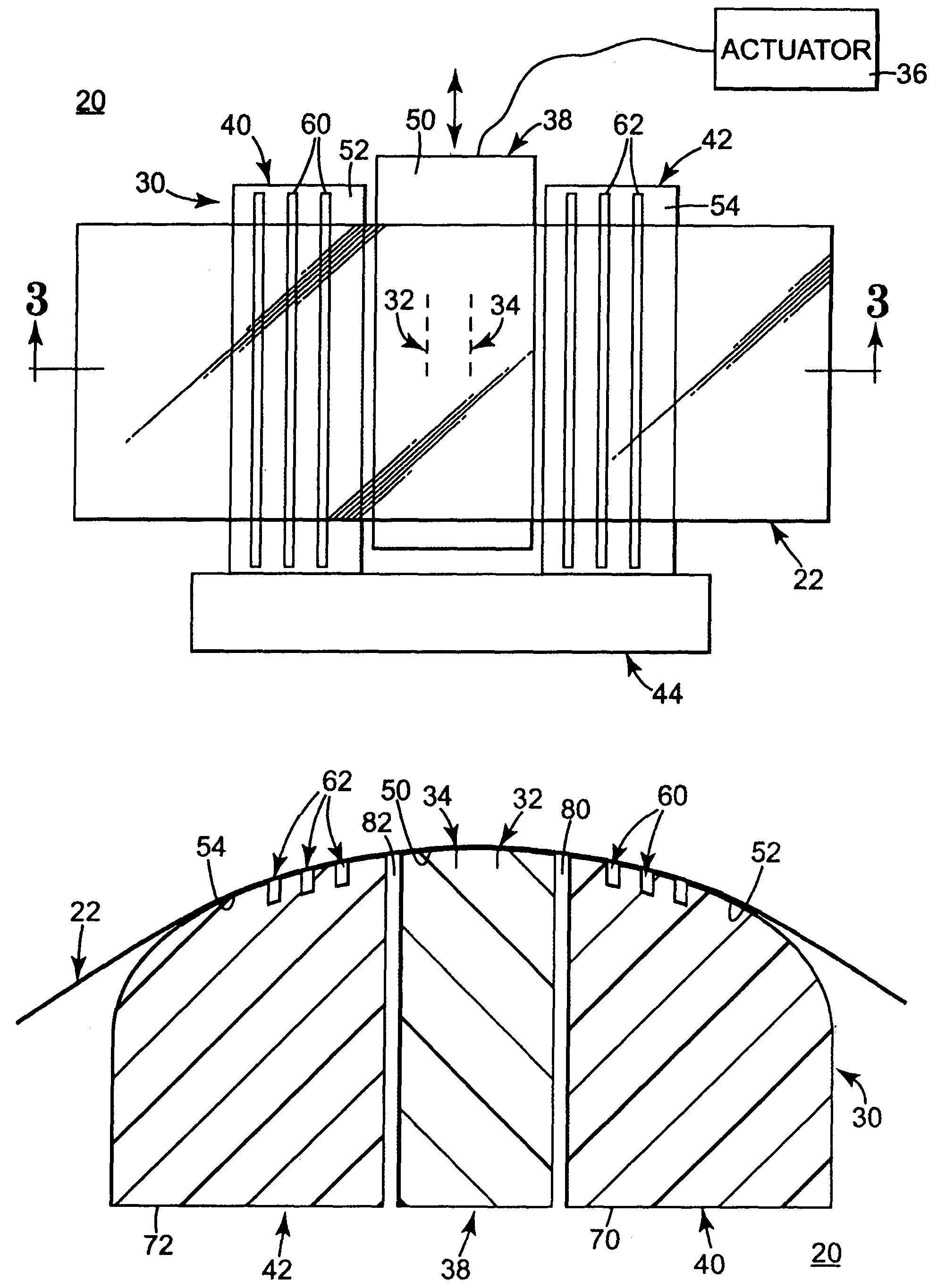
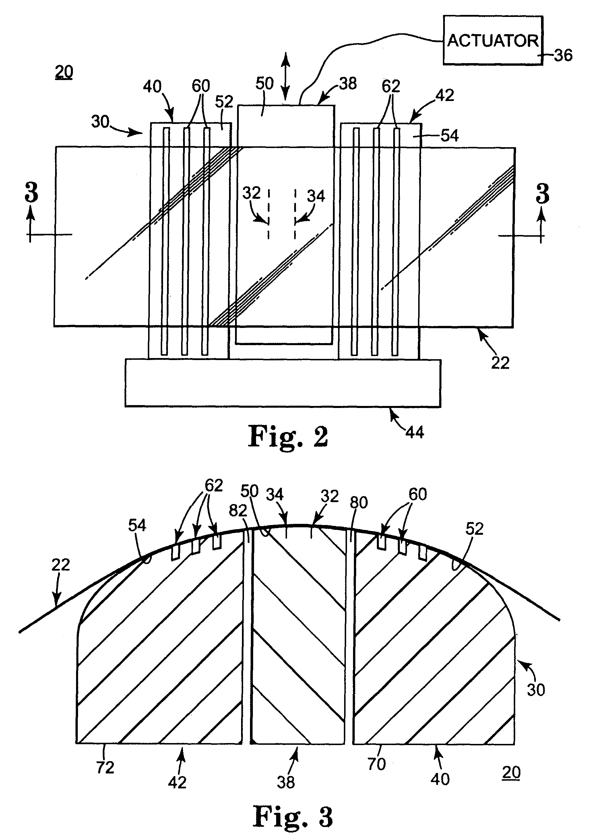
[0017]FIGS. 2 and 3 illustrate various views of a magnetic head assembly 20 for recording, reproducing, and / or erasing magnetic information in a track of a flexible, magnetic tape 22 in accordance with the present invention. For ease of illustration, the tape 22 is shown in FIG. 2 as being transparent to facilitate identification of components behind the tape 22. It should be understood, however, that the tape 22 can assume a wide variety of forms known in the art, and thus may not be transparent.

[0018]The magnetic head assembly 20 includes a magnetic head 30, read / write elements 32, 34, and an actuator 36 (shown in block form). As described in greater detail below, the read / write element 32, 34 are maintained by the magnetic head 30, and in particular by a central section 38 thereof. The central section 38 is laterally moveable relative to other portions of the magnetic head 30, and is connected to the actuator 36. In general terms, during use, as the tape 22 is moved across the ma...


PUM

PropertyMeasurementUnit
pressureaaaaaaaaaa
magneticaaaaaaaaaa
widthaaaaaaaaaa

Abstract

A magnetic head assembly in a linear tape system. The magnetic head assembly includes a magnetic head having a central section, a first outrigger, and a second outrigger. The central section maintains at least one read / write element. The first outrigger is positioned adjacent the central section and forms at least one air bleed slot. The second outrigger is positioned adjacent the central section opposite the first outrigger and also forms at least one air bleed slot. Finally, the central section is laterally moveable relative to the outriggers. With this configuration, the moveable, central section, otherwise used for lateral positioning of the read / write element relative to a magnetic tape, is separated from the outriggers that otherwise minimize a fly height between the magnetic tape and the outriggers.

Description

CROSS-REFERENCE TO RELATED APPLICATIONS[0001]This application is related to, and incorporates by reference an entirety of, U.S. patent application Ser. No. 10 / 452,334 entitled “Data Storage Tape Cartridge With Subambient Pressure Feature,” filed on even date herewith, now U.S. Pat. No. 6,874,720.BACKGROUND OF THE INVENTION[0002]The present invention relates to magnetic tape read / write heads. More particularly, it relates to a magnetic tape head assembly adapted to facilitate lateral movement of a read / write element relative to other head assembly components.[0003]Magnetic tape systems for recording, reproducing, and / or erasing magnetic information in a linear tape system generally consists of a magnetic tape traveling along a magnetic head assembly. The magnetic head assembly includes a magnetic head that provides a surface (typically contoured) for guiding the magnetic tape across one or more read / write elements otherwise maintained by the head. A common concern associated with the...

Claims


Application Information

Patent Timeline
Patent Type & Authority Patents(United States)
IPC IPC(8): G11B5/54G11B5/187G11B5/265G11B5/584
CPCG11B5/1871G11B5/265G11B5/60G11B5/255G11B5/584G11B5/3106
Inventor JOHNSON, DOUGLAS W.ZWETTLER, CHRISTOPHER J.FAHIMI, SAEED A.
Owner IMATION
Why Eureka
Try Eureka