
Information recording device

a recording device and information technology, applied in the field of information recording devices, can solve the problems of inability to obtain uniform mark width, limitation of pulse width and recording allowable values, and difficulty in setting the optimum recording condition

Active Publication Date: 2006-02-28
RICOH KK
View PDF23 Cites 44 Cited by
  • Summary
  • Abstract
  • Description
  • Claims
  • Application Information

AI Technical Summary

Benefits of technology

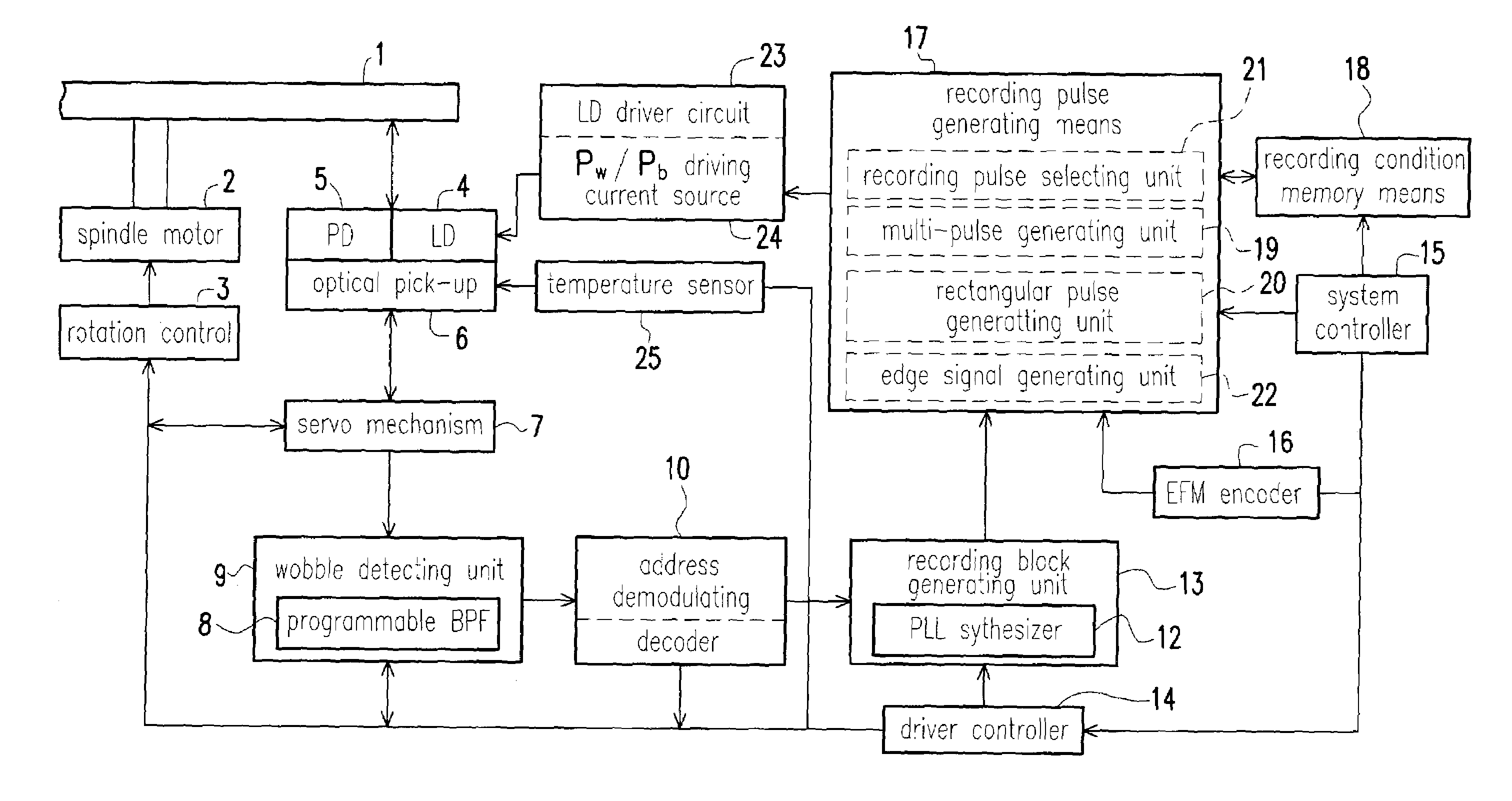
The present invention provides an information recording device that can select the best recording pulse for a given recording condition, even if the recording power is insufficient. The device can also predict the sensitivity reduction of the recording medium and change the light-emission waveform of the recording pulse accordingly. This allows for faster recording and better recording quality, regardless of the recording medium's characteristics. The device uses a recording linear velocity as the recording condition, and can switch between multi-pulse and rectangular pulse based on the recording condition to achieve high-speed recording. The device also includes a velocity information acquiring means and a rectangular pulse calculation means to optimize the recording performance.

Problems solved by technology

Therefore, the ratio to the recording clock period T of the optimum heating pulse is different and therefore a uniform mark width cannot be obtained.
However, there is a limitation in the settings of the pulse widths and the allowable values of the recording powers that the information recording device sets.
Even though the settings are based on the recording condition assigned by pre-formatted information of the optical disc medium, there is difficulty in setting the optimum recording condition.
Namely, when the recording sensitivity of DVD-R, etc. using coloring matter is reduced because the wavelength of the output laser beam shifts to the long wavelength side, the optimum recording power obtained by the test writing, etc. is deviated by the wavelength shift, so that a good recording is difficult to obtain.

Method used


Image

  • Information recording device
  • Information recording device
  • Information recording device

Examples


Embodiment Construction

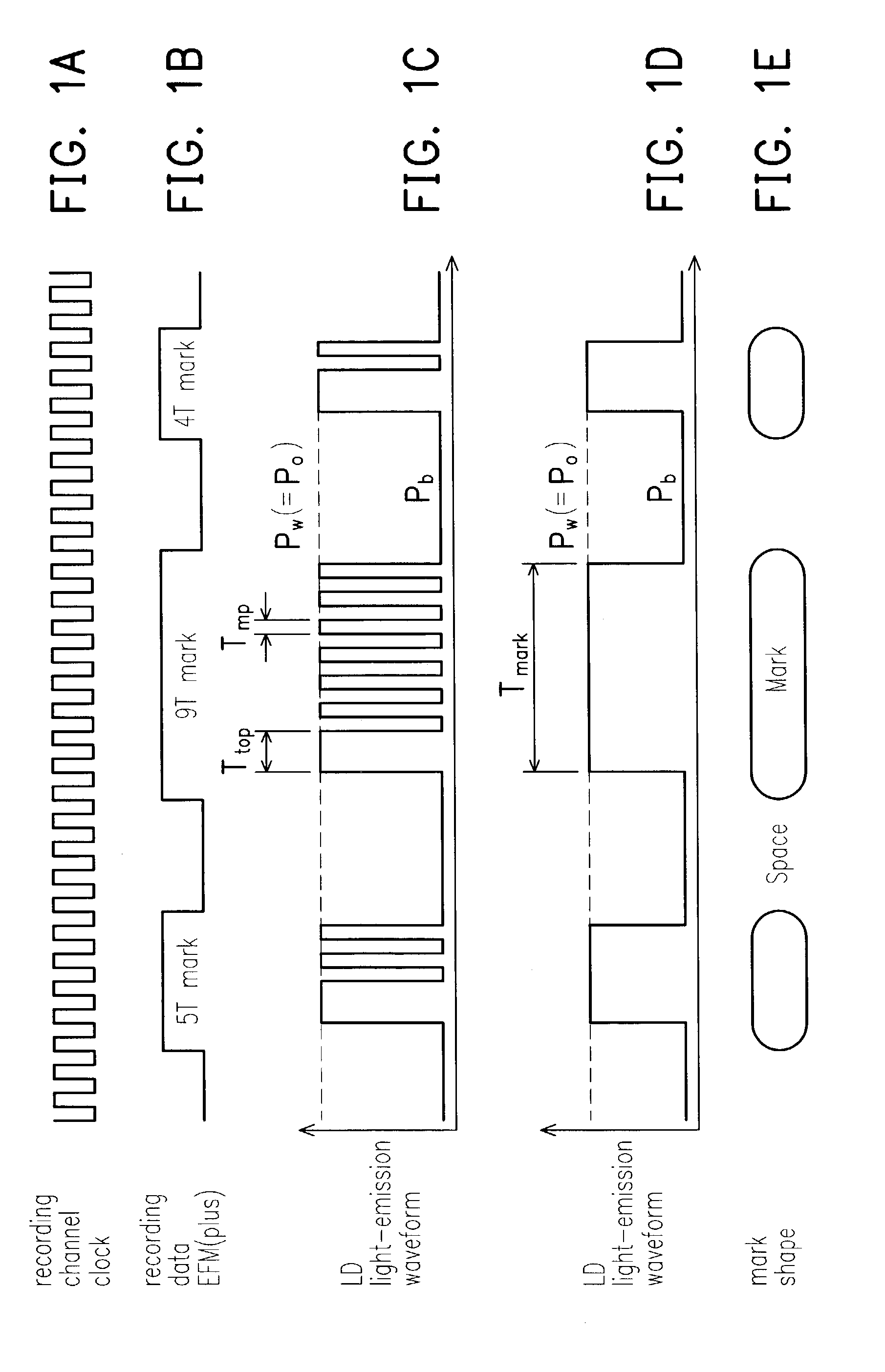
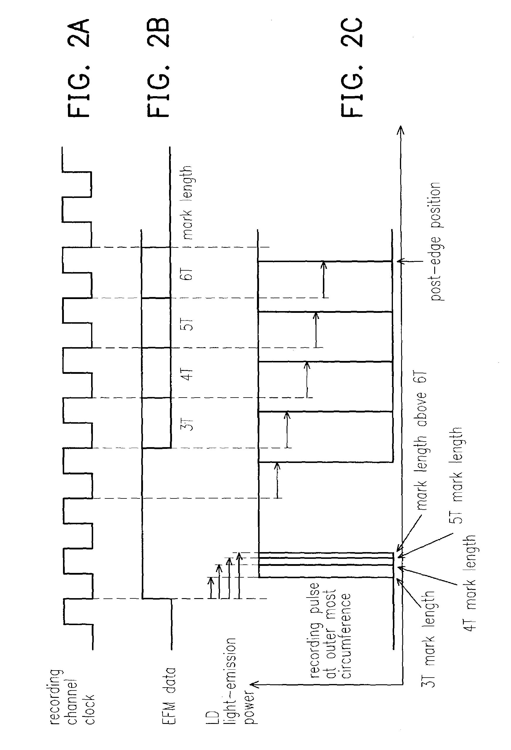
[0044]The embodiment of the invention is described in detail accompanying with the attached drawings FIGS. 1A˜9D. First, information recording method, which is suitable for the information recording device of the embodiment of the present invention, is described.

Recording Method I

[0045]In the embodiment, the write-once type optical disc using coloring matter, such as DVD-R, is used as an optical recording medium that is an object to be recorded. In addition, a multi-pulse is assumed to use as the recommended recording pulse.

[0046]Referring to FIG. 1C, as a basic recording pulse using for the optical recording medium such as DVD-R, a recording pulse train with respect to each mark data length nT as shown in FIG. 1B (where T represents the period of the recording channel clock and n is a nature number. For the EFM (plus) modulation, n≈3˜11, 14.) is constructed by a multi-pulse that comprises a leading heating pulse portion and a plurality of succeeding heating pulse portions. The sett...


PUM

PropertyMeasurementUnit
clock frequencyaaaaaaaaaa
linear velocityaaaaaaaaaa

Abstract

An information recording device comprising at least a recording pulse generating means and a recording pulse selecting means capable of generating various multi-pulses each of which is a combination of a leading heating pulse and a succeeding heating pulse, and rectangular pulses each of which is a single pulse, as a recording pulse, is disclosed. The recording pulse selecting means switches and selects among the multi-pulses and the rectangular pulses according to a recording condition, and then causes a light emission of a laser light source through a light source driving means. Even though in a high recording linear velocity recording condition that is insufficient in power for the recommended multi-pulse recording, a very low recording power can still be used by switching to the rectangular pulse recording, so as to achieve a recording with a much higher recording speed. In addition, good recording marks can be formed without exceeding a maximum allowable recording power.

Description

CROSS-REFERENCE TO RELATED APPLICATION[0001]This application claims the priority benefit of Japanese application serial no. 2002-001685, filed on Jan. 8, 2002.BACKGROUND OF THE INVENTION[0002]1. Field of the Invention[0003]This invention relates in general to an information recording device for an optical disc medium, for example, a reproduction-only DVD (digital video disc, or disc versatile disc) medium such as a DVD-Video or a DVD-ROM, or a DVD-Recordable (DVD-R) with format exchangeability.[0004]2. Description of Related Art[0005]As multimedia gets more popular than ever, reproduction-only medium such as DVD-Video or DVD-ROM, or information recording medium such as write-once-type DVD-R using coloring matter as a recording layer is developed.[0006]Information (sector, for example) recorded on such DVD medium is a format as shown in FIG. 9A. As shown in FIG. 9D, in this format, data is continuously recorded with a constant linear density on the whole track of the medium. Conventi...

Claims


Application Information

Patent Timeline
Patent Type & Authority Patents(United States)
IPC IPC(8): G11B7/0045G11B7/125G11B7/1267
CPCG11B7/1267G11B7/00456
Inventor YOKOI, KENYA
Owner RICOH KK
Learn More