Blow-by gas separator

Inactive Publication Date: 2006-03-07
YAMAHA MOTOR CO LTD
View PDF4 Cites 46 Cited by
  • Summary
  • Abstract
  • Description
  • Claims
  • Application Information

AI Technical Summary

Problems solved by technology

However, the desired performance does not always occur under all running conditions and with all engines, particularly with engines where pressure in the induction system can at times be greater than atmospheric.

Method used


Image

  • Blow-by gas separator
  • Blow-by gas separator
  • Blow-by gas separator

Examples


Embodiment Construction

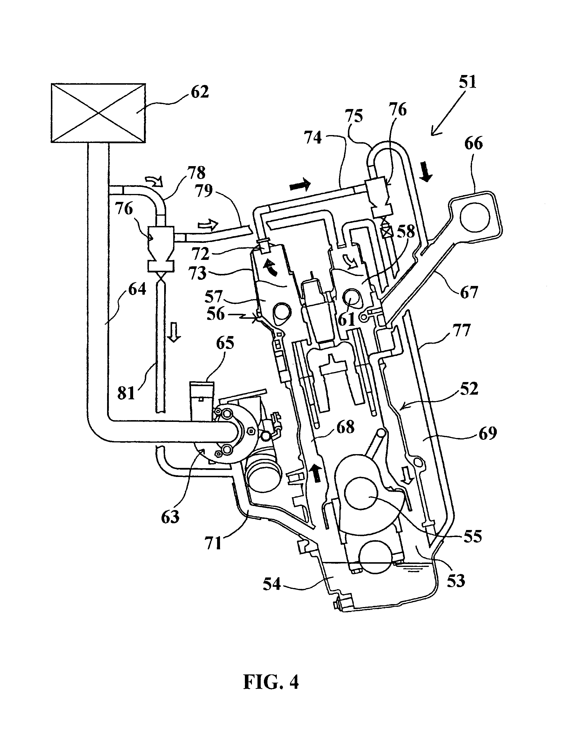
[0019]Referring now in detail to the drawings and initially to FIGS. 4 and 5, these are cross sectional views taken through a single cylinder of an internal combustion engine constructed in accordance with an embodiment of the invention, which engine is indicated generally by the reference numeral 51. Basically, except for the crankcase ventilation system and the oil separator therefore, the engine 51 may be of any general type and although the invention has particular utility in conjunction with engines that are either supercharged by turbo charging or otherwise.

[0020]The engine 51 includes a cylinder block assembly 52 in which a plurality of cylinder bores are formed. Although the described embodiment illustrates an in-line engine, it should be readily apparent that the engine may be of any type including V-type or opposed engines and engines having any number of cylinders. At the lower end of the cylinder block 52 there is formed a crankcase chamber 53 in which lubricant is conta...


PUM


Abstract

An improved crankcase ventilation system including an improved blow-by gas separator wherein it will be insured that oil cannot accumulate in the separator chamber under any running conditions so that the oil is totally precluded from being able to pass into the induction system.

Description

BACKGROUND OF INVENTION[0001]This invention relates to a blow-by gas separator and more particularly to an improved separation system for use with internal combustion engines in connection with crankcase gas recirculation.[0002]In order to improve the emission qualities of internal combustion engines, they have been provided with recirculated crankcase ventilation systems wherein the blow-by gases from the crankcase are returned to the combustion chambers for further combustion of undesirable constituents such as hydrocarbons. The conventional type of system employs a combined oil separator and oil return device that receives the crankcase gases and separates oil from them with the separated oil being returned to the crankcase chamber. The thus purified crankcase gases are then delivered to the induction system for introduction into the combustion chambers wherein any unburned hydrocarbons that have not been separated can be reduced by further combustion.[0003]FIGS. 1 through 3 are ...

Claims


Application Information

Patent Timeline
Patent Type & Authority Patents(United States)
IPC IPC(8): F02B25/06F01M13/00F01M13/02F01M13/04F02M25/06F02M35/10
CPCF01M13/022F01M13/04F02M25/06F02M35/10222F01M2013/027F01M2013/0427Y02T10/121F02M35/10098F02M35/112F01M2013/0488Y02T10/12
Inventor TAKAHASHI, YUKINORIONO, KATSUMASAMORI, TAKAO
Owner YAMAHA MOTOR CO LTD
Why Eureka
Try Eureka