Crankcase ventilation system

a ventilation system and crankcase technology, applied in the direction of machines/engines, mechanical equipment, non-fuel substance addition to fuel, etc., can solve the problems of blow-by gas contaminant harmful to the environment, poor choice of direct atmospheric ventilation, and short time-consuming to clean up

Active Publication Date: 2006-03-30
CATERPILLAR INC
View PDF41 Cites 19 Cited by
  • Summary
  • Abstract
  • Description
  • Claims
  • Application Information

AI Technical Summary

Benefits of technology

[0011] In another aspect, the present disclosure is directed to a method for crankcase ventilation. The method may include venting crankcase gases from a crankcase of an internal combustion engine and routing the crankcase gases away from the crankcase in a first conduit. Exhaust gases from one or more combustion chambers of the internal combustion engine may be vented and routed away from the one or more combustion chambers in a second conduit. Particulates may be filtered from the exhaust gases with a particulate trap and crankcase gases may be merged with the filtered exhaust gases at a point downstream from the particulate trap.

Problems solved by technology

However, the contaminants in blow-by gases are harmful to the environment.
Therefore, emissions concerns make direct atmospheric venting a poor option under most, if not all, operating conditions.
However, in an engine with forced induction, returning crankcase gases to the intake side of a compressor in a supercharger or turbocharger can result in fouling of the compressor wheel in a relatively short time period.
Further, even with extensive purification, some level of contamination may still exist that may be harmful to the supercharger or turbocharger or various engine components.
Systems have been developed for engines with forced induction that vent the crankcase gases to the atmosphere after the purification process, rather than introducing them back into the engine for further combustion and potentially fouling or otherwise inhibiting the performance of the supercharger or turbocharger.
While the system of Liang successfully releases purified crankcase gases to the atmosphere, this system is complex.

Method used


Image

  • Crankcase ventilation system
  • Crankcase ventilation system
  • Crankcase ventilation system

Examples


Embodiment Construction

[0014] Reference will now be made in detail to the drawings. Wherever possible, the same reference numbers will be used throughout the drawings to refer to the same or like parts.

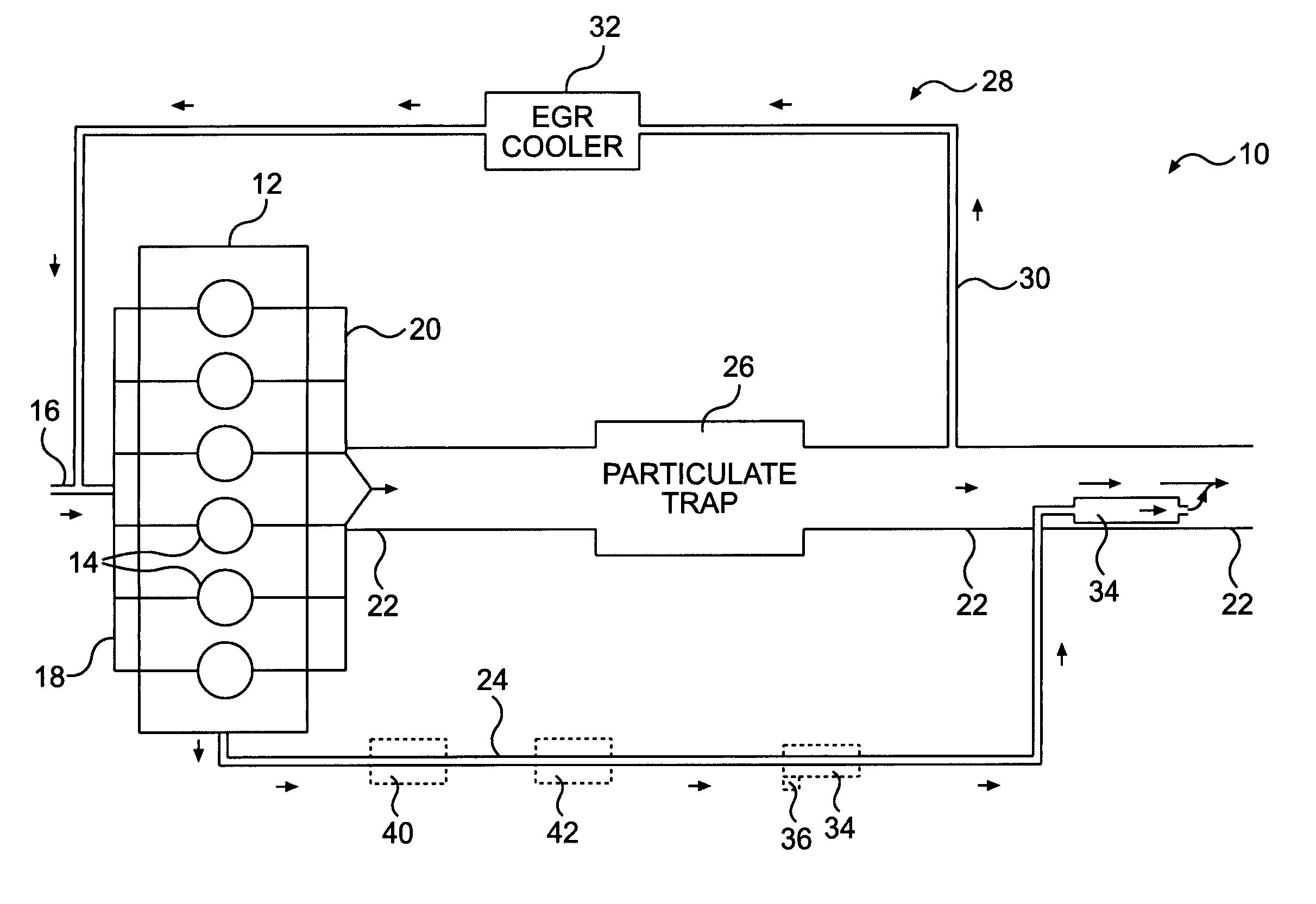
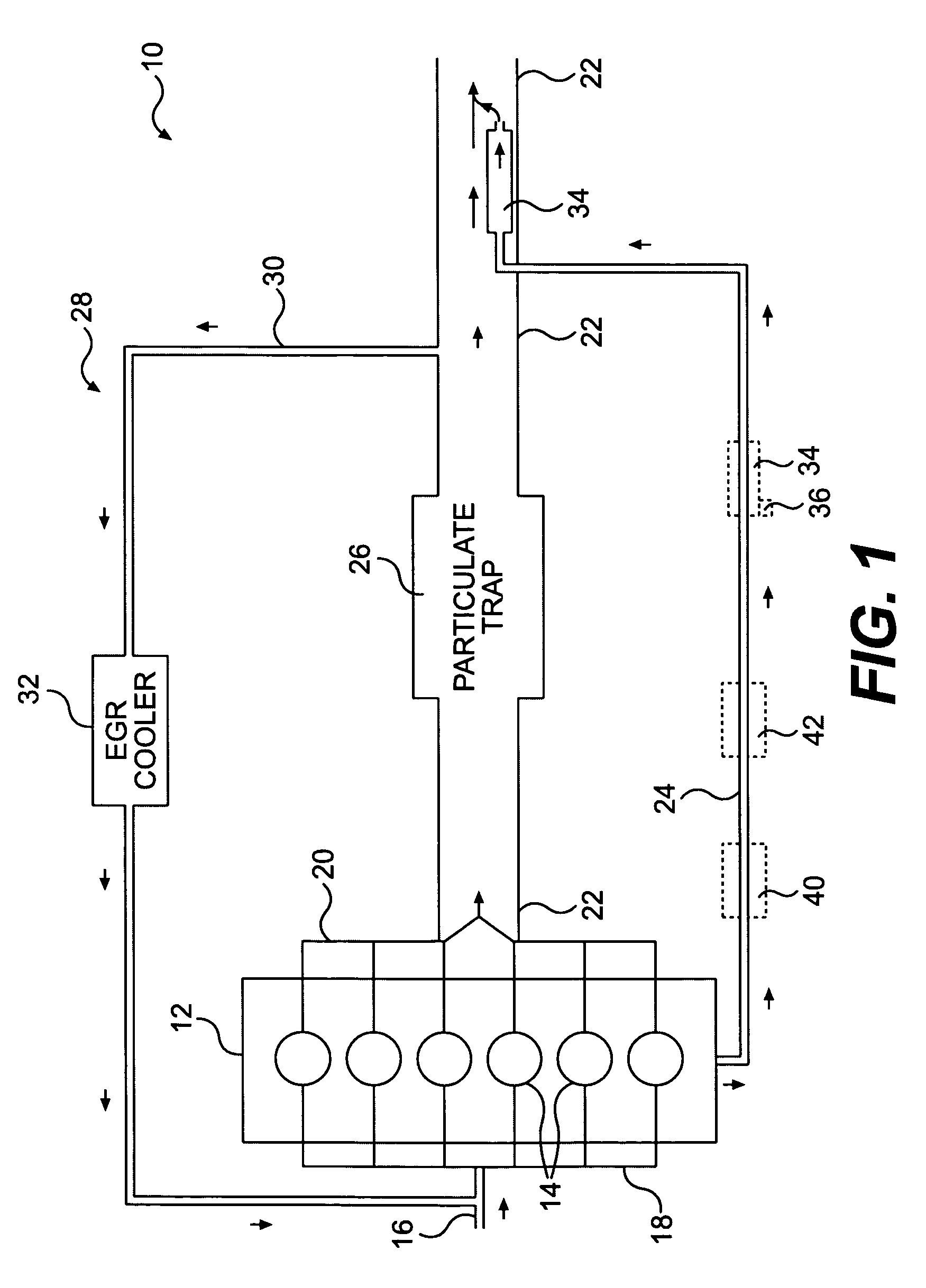
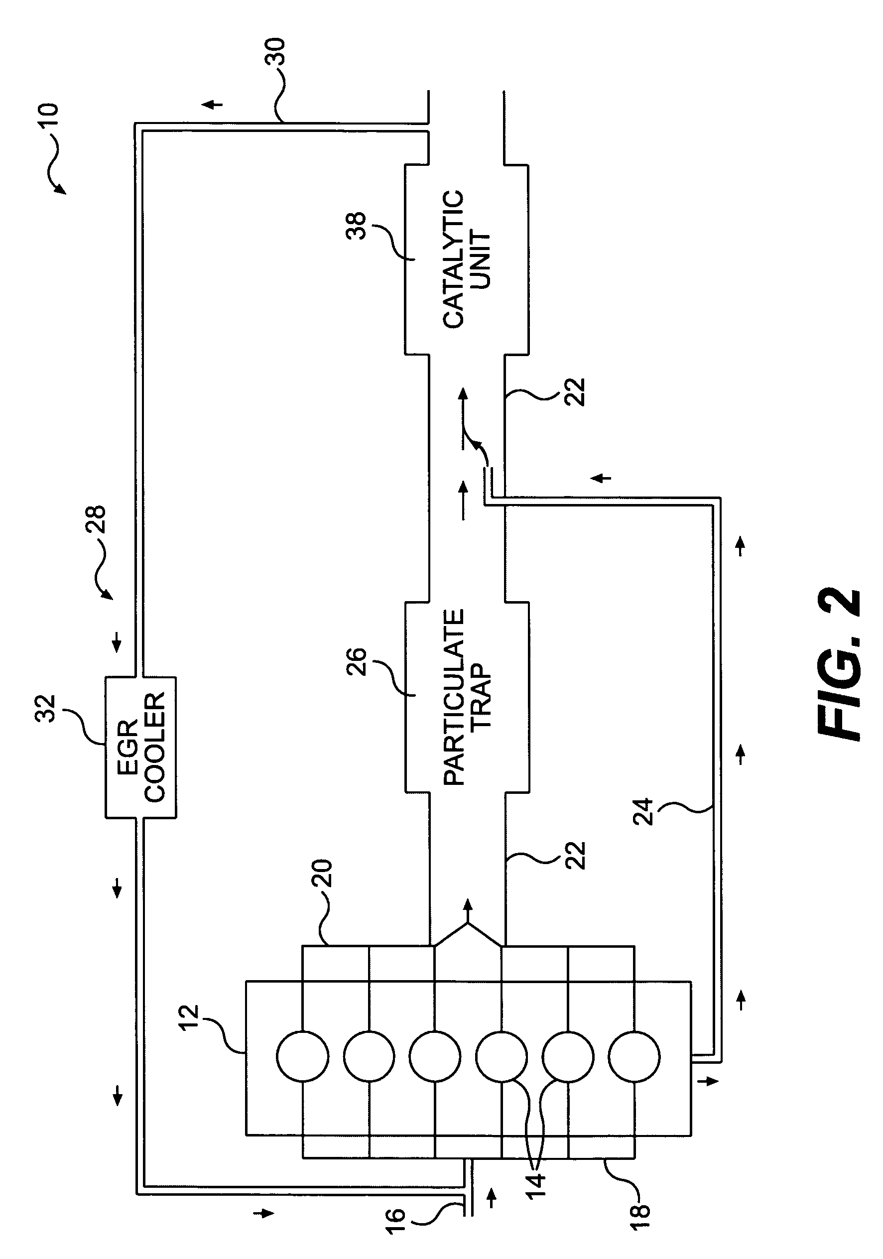
[0015]FIG. 1 illustrates an exemplary crankcase ventilation (CCV) system 10. CCV system 10 may include an internal combustion engine 12. Engine 12 may include combustion cylinders 14, and may have intake and exhaust components attached to it, such as, for example, an air intake 16, an intake manifold 18, an exhaust manifold 20, a main exhaust conduit 22, and a CCV conduit 24.

[0016] Engine 12 may be any kind of internal combustion engine. For example, engine 12 may be a gasoline engine or a diesel engine. Further, engine 12 may be naturally aspirated or may include forced induction such as turbocharging or supercharging.

[0017] CCV system 10 may include one or more exhaust treatment devices for reducing emissions in the exhaust gas from engine 12. In particular, CCV system 10 may include a particulate trap...


PUM


Abstract

A crankcase ventilation system may include a first exhaust flow path configured to permit flow of main exhaust gases from a combustion chamber of an internal combustion engine and a particulate trap disposed in the first exhaust flow path. The system may also include a second exhaust flow path configured to enable flow of crankcase gases from a crankcase of the internal combustion engine and to merge the crankcase gases with the main exhaust gases at a point in the first exhaust flow path located downstream of the particulate trap.

Description

TECHNICAL FIELD [0001] This disclosure is directed to an exhaust system for internal combustion engines and, more particularly, to a crankcase ventilation system for internal combustion engines. BACKGROUND [0002] In internal combustion engines, including diesel and gasoline engines, a fuel and air mixture is combusted in combustion cylinders. Reciprocating pistons in the combustion cylinders are moved between top dead center and bottom dead center positions by a crankshaft below the cylinders in a crankcase. As each piston moves toward its top dead center position, it compresses the fuel and air mixture in the combustion chamber above the piston. The compressed mixture combusts and expands, driving the piston downward toward its bottom dead center position. [0003] Combustion in the cylinder releases energy and generates combustion products and by-products, most of which are exhausted from the cylinder into an exhaust system of the engine during the exhaust phase of the combustion cy...

Claims


Application Information

Patent Timeline
Patent Type & Authority Applications(United States)
IPC IPC(8): F01N3/00F02M25/06
CPCF01M13/00F01N3/10F01N3/035
Inventor OPRIS, CORNELIUS N.
Owner CATERPILLAR INC
Why Eureka
Try Eureka