Oil-gas separator assembly of crankcase ventilation system

A technology of oil-gas separator and crankcase ventilation, which is applied in the direction of crankcase ventilation, machine/engine, engine components, etc. It can solve the problems of difficult integrated layout and large volume, and achieve small space occupation, simple structure and good oil-gas separation effect Effect

Inactive Publication Date: 2013-01-02
CHERY AUTOMOBILE CO LTD
View PDF3 Cites 16 Cited by
  • Summary
  • Abstract
  • Description
  • Claims
  • Application Information

AI Technical Summary

Problems solved by technology

[0002] At present, my country's vehicle emission regulations are becoming more and more stringent, so the requirements for engine design are also constantly improving. For the engine body, the curved system is a major link that affects emission control. How to better control the emissions from the curved system? It is a pro

Method used


Image

  • Oil-gas separator assembly of crankcase ventilation system
  • Oil-gas separator assembly of crankcase ventilation system

Examples


Embodiment 1

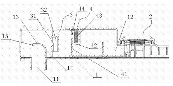
[0017] Such as figure 1 As shown, the crankcase ventilation system oil-gas separator assembly of this embodiment includes a housing 1 having an air inlet 11 and an air outlet 12, the air outlet 12 is connected with a PCV valve 2, and the housing 1 is sequentially arranged with Centrifugal oil and gas separation device 3, fiber oil absorption device 4.

[0018] in:

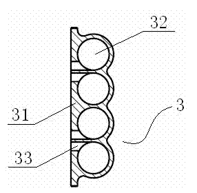
[0019] The centrifugal oil-gas separation device 3 includes a first partition 31 whose periphery is in contact with the inner wall of the casing 1 and four cylinders 32 arranged on the same side of the first partition 31; the top of the cylinder 32 is closed and the bottom is open; the first partition The plate 31 is provided with a first vent 33 communicating with the cylinder 32 , and the first vent 33 is tangent to the cylinder wall of the cylinder 32 .

[0020] The fiber oil-absorbing device 4 includes a second partition 41 whose periphery is connected to the inner wall of the housing 1 and a cavity 42 locate...


PUM


Abstract

The invention aims at providing an oil-gas separator assembly of a crankcase ventilation system with small occupied space and high oil-gas separation efficiency. The oil-gas separator assembly of the crankcase ventilation system disclosed by the invention comprises a case provided with an air inlet and an air outlet, wherein the air outlet is connected with a PCV (pollution-control valve), and the oil-gas separator assembly is characterized in that the case is internally provided with a centrifugal oil-gas separation device and a fiber oil absorption device along an airflow advancing direction. The centrifugal oil-gas separation device and the fiber oil absorption device are arranged, two-stage oil-gas separation is adopted, the oil-gas separation effect can be improved, and the centrifugal oil-gas separation device occupies small space, so that the centrifugal oil-gas separation device can be conveniently arranged.

Description

technical field [0001] The invention relates to an oil-gas separator assembly of an engine crankcase ventilation system. Background technique [0002] At present, my country's vehicle emission regulations are becoming more and more stringent, so the requirements for engine design are also constantly improving. For the engine body, the curved system is a major link that affects emission control. How to better control the emissions from the curved system? It is a problem that must be solved to reduce the oil content in the exhaust gas of the winding system. Although there are many types of oil-gas separators at present, there is a common problem, that is, the labyrinth is used for oil-gas separation, so the volume is large and it is difficult to Integrated in the valve compartment cover. Contents of the invention [0003] The object of the present invention is to propose an oil-gas separator assembly for a crankcase ventilation system with small space occupation and high oil...

Claims


Application Information

Patent Timeline
IPC IPC(8): F01M13/04
Inventor 徐勇祖松刘广志
Owner CHERY AUTOMOBILE CO LTD
Why Eureka
Try Eureka