Internal combustion engine ignition apparatus

a technology of ignition apparatus and internal combustion engine, which is applied in the direction of ignition automatic control, electric control, machines/engines, etc., can solve the problems of affecting the timing, degrading the ignition characteristic, and the reference potential level of the ignition signal voltage disturbing the timing, so as to avoid the degradation of the ignition characteristic and simplify the terminal structure

Active Publication Date: 2006-03-07
MITSUBISHI ELECTRIC CORP
View PDF8 Cites 4 Cited by
  • Summary
  • Abstract
  • Description
  • Claims
  • Application Information

AI Technical Summary

Benefits of technology

[0010]The present invention proposes an internal combustion engine ignition apparatus which is improved, in a switching circuit having no power supply terminal connected to a battery and having an output terminal, an input terminal and a reference potential terminal, so that an ignition characteristic is not degraded by a variation in the reference potential level of an ignition signal voltage.
[0014]In the internal combustion engine ignition apparatus of the invention, the switching circuit does not have the power supply terminal connected to a battery, but has the three terminals of the output terminal, the input terminal and the reference potential terminal, and the terminal structure can be simplified. In addition, the current supply circuit includes the waveform shaping circuit, the waveform shaping circuit includes the comparison signal generation circuit for generating the comparison signal on the basis of the ignition signal voltage, and the reference signal generation circuit for generating the reference signal on the basis of the ignition signal voltage, starts to supply the driving current to the drive resistor from the current supply circuit when the comparison signal becomes larger than the reference signal in the rising portion of the ignition signal voltage, and interrupts the driving current when the comparison signal becomes smaller than the reference signal in the falling portion of the ignition signal voltage. Accordingly, even if the reference potential level of the ignition signal voltage is varied, the switching element can be certainly turned on and off at more accurate timings, and the degradation of an ignition characteristic can be avoided.

Problems solved by technology

However, since the four terminals including the power supply terminal is included, the terminal structure becomes complicated.
However, in the internal combustion engine ignition apparatus of this type which has no power supply terminal connected to a battery, since a switching element connected to the primary coil of the ignition coil is directly driven by the ignition signal voltage supplied to the input terminal, there is a disadvantage that variation in the reference potential level of the ignition signal voltage disturbs the timings when the switching element is turned on and off and degrades the ignition characteristic.
However, the variation in the base voltage included in the ignition signal voltage disturbs these timings and degrades the ignition characteristic of the ignition apparatus.
Besides, the variation in the ignition timing varies an ignition timing to an engine, and lowers the output of the internal combustion engine.
At the worst, due to a rise in the level of the ignition signal voltage, it becomes impossible to turn off the switching element in the falling portion of the ignition signal voltage, and misfire is caused.

Method used


Image

  • Internal combustion engine ignition apparatus
  • Internal combustion engine ignition apparatus
  • Internal combustion engine ignition apparatus

Examples


embodiment 1

[0030

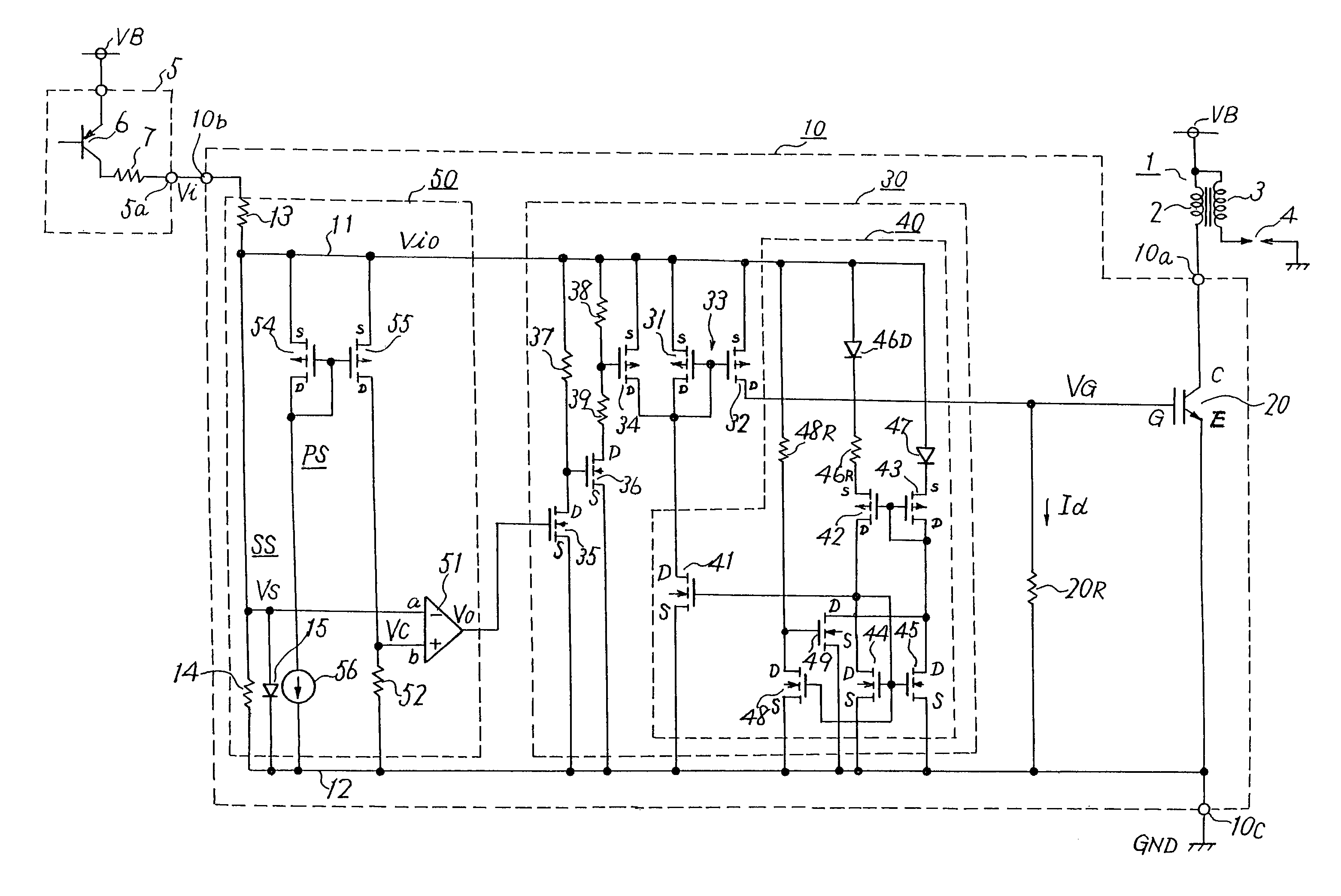
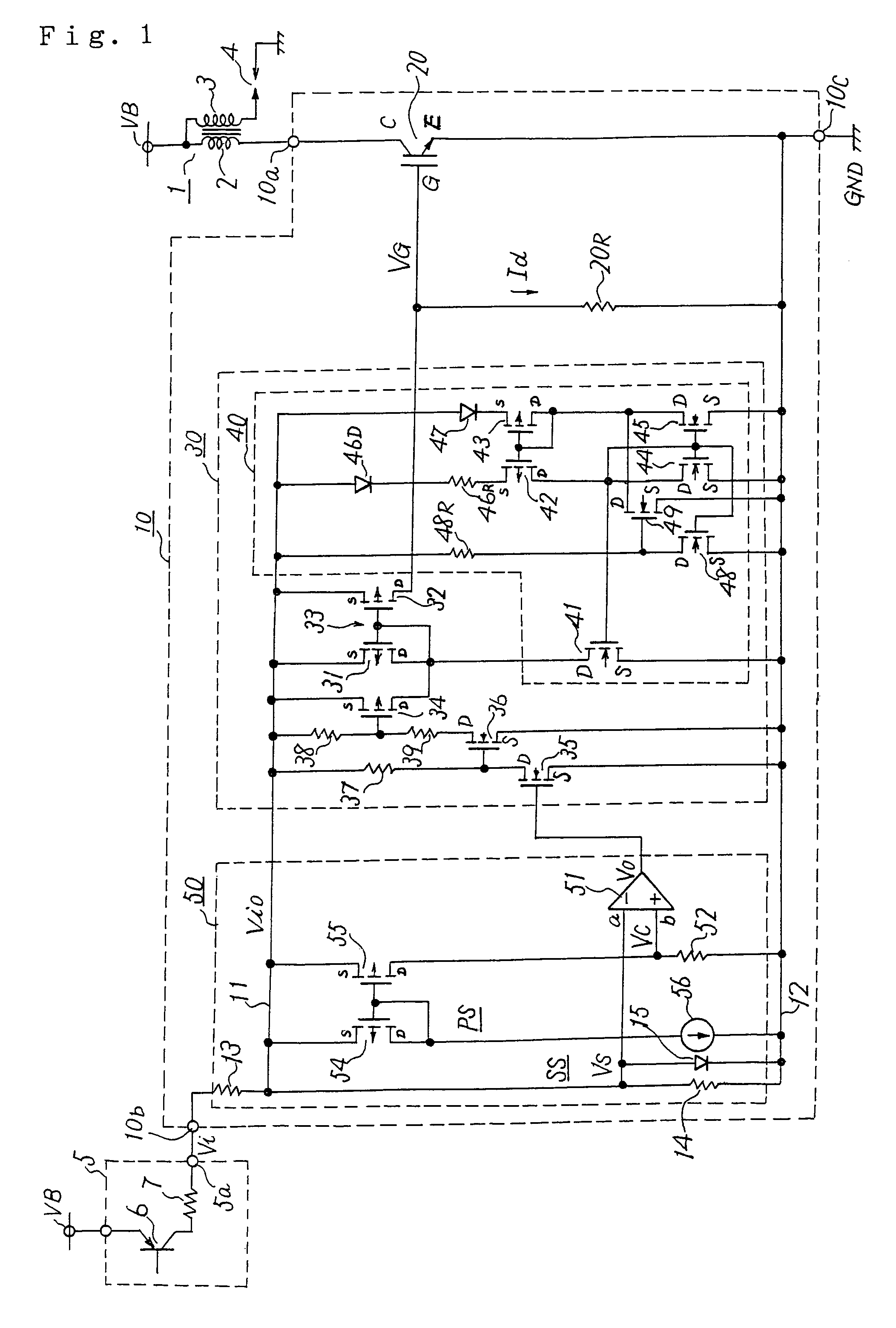
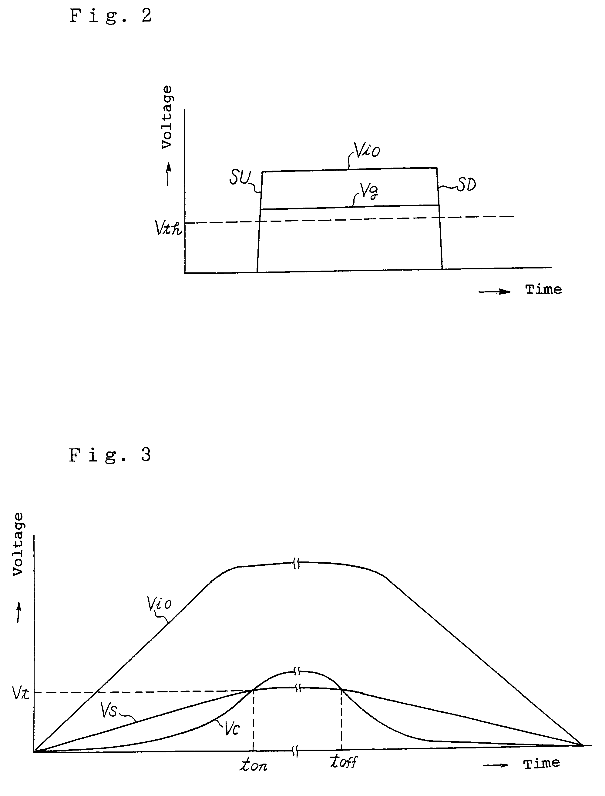
[0031]FIG. 1 shows embodiment 1 of an internal combustion engine ignition apparatus of the invention. FIGS. 2 and 3 are characteristic diagrams for explaining the operation of the embodiment 1.

[0032]The internal combustion engine ignition apparatus of the embodiment 1 is an ignition apparatus for an internal combustion engine mounted in an automobile, and includes an ignition coil 1, an ignition driving circuit 5, and a switching circuit 10. The ignition coil 1 includes a primary coil 2 and a secondary coil 3 and is connected to a power supply terminal VB such as an on-board battery. The on-board battery has, for example, 12 volts, and the power supply terminal VB has, for example, 12 volts. A spark plug 4 is connected to the secondary coil 3. This spark plug 4 is disposed in a combustion chamber of the internal combustion engine, and ignites fuel, such as gasoline, supplied into the combustion chamber to burn it.

[0033]The ignition driving circuit 5 is included in an electrical...

embodiment 2

[0061

[0062]FIG. 4 shows embodiment 2 of an internal combustion engine ignition apparatus of the invention, and FIG. 5 is an explanatory diagram of the operation of the embodiment 2.

[0063]The embodiment 2 shown in FIG. 4 includes a switching circuit 10A. The switching circuit 10A is constructed by three terminals, that is, an output terminal 10a, an input terminal 10b and a reference potential terminal 10c similarly to the switching circuit 10 shown in FIG. 1. The input terminal 10a is directly connected to a primary coil 2 of an ignition coil 1, the input terminal 10b is directly connected to an ignition signal terminal 5a of an ignition driving circuit 5, and the reference potential terminal 10c is directly connected to a reference potential point GND.

[0064]This switching circuit 10A includes a waveform shaping circuit 50A instead of the waveform shaping circuit 50 of FIG. 1, and in this embodiment 2, instead of the ignition signal line 11 of FIG. 1, an ignition signal line 11a dir...

embodiment 3

[0076

[0077]FIG. 6 shows embodiment 3 of an internal combustion engine ignition apparatus of the invention. This embodiment 3 uses a switching circuit 10B. The switching circuit 10B is such that a current limiting circuit 60 is added to the switching circuit 10 of the embodiment 1 shown in FIG. 1. Along with this, instead of the switching element 20 shown in FIG. 1, a switching element 20A having an auxiliary emitter E1 is used. Since the others are constructed similarly to the embodiment 1 of FIG. 1, the same parts are denoted by the same symbols and the explanation will be omitted. Incidentally, in this embodiment 3, the waveform shaping circuit 50A shown in FIG. 4 is used.

[0078]The switching element 20A is an IGBT, and this includes a collector C, a main emitter E, the auxiliary emitter E1, and a gate G. The collector C is directly connected to an output terminal 10a of the switching circuit 10B, and the main emitter E is directly connected to a reference potential terminal 10c th...


PUM


Abstract

An internal combustion engine ignition apparatus includes a switching circuit having no power supply terminal connected to a power supply such as a battery is constructed, and including an output terminal connected to an ignition coil, an input terminal for receiving an ignition signal voltage and a reference potential terminal connected to a reference potential. In the switching circuit, the terminal structure is simplified, and energization timing and ignition timing can be set more accurately. A current supply circuit is connected between the input terminal and the reference potential terminal, and a current is supplied from the current supply circuit to a drive resistor of the switching element. In this current supply circuit, an energization timing when supply of the driving current is started is controlled by a waveform shaping circuit operating by the ignition signal voltage, and an ignition timing when the driving current is interrupted is controlled.

Description

BACKGROUND OF THE INVENTION[0001]1. Field of the Invention[0002]The present invention relates to an internal combustion engine ignition apparatus mounted in, for example, an automobile, and particularly to an internal combustion engine ignition apparatus in which a current of a primary coil of an ignition coil is interrupted by a switching element, so that a high voltage for ignition is generated in a secondary coil of the ignition coil.[0003]2. Description of the Related Art[0004]In a conventional internal combustion engine ignition apparatus, as a switching circuit for opening and closing a switching element connected to a primary coil of an ignition coil, one having a power supply terminal connected to a battery, an output terminal connected to the primary coil of the ignition coil, an input terminal to which an ignition signal voltage is supplied, and a reference potential terminal is often used. In the internal combustion engine ignition apparatus having the four terminals of t...

Claims


Application Information

Patent Timeline
Patent Type & Authority Patents(United States)
IPC IPC(8): F02P5/145F02P3/04F02P1/08F02P3/045F02P3/05
CPCF02P1/083F02D2041/2058F02D2041/2075F02P3/051F02P3/0453
Inventor NARUSE, YUSUKENOBE, HISANORI
Owner MITSUBISHI ELECTRIC CORP
Why Eureka
Try Eureka