
Rotating electrical device

a technology of electrical devices and windings, which is applied in the direction of electrical apparatus, dynamo-electric machines, windings, etc., can solve the problems of increased cost and achieve the effects of increasing cost, increasing cost, and complex structure of the terminals for wiring-in the windings

Active Publication Date: 2017-03-28
DENSO CORP
View PDF4 Cites 1 Cited by
  • Summary
  • Abstract
  • Description
  • Claims
  • Application Information

AI Technical Summary

Benefits of technology

The present invention provides a rotating electrical device that can suppress an increase in cost associated with complex and expensive winding structures. This is achieved by simplifying the structure of the terminals for wiring in the windings and facilitating high-speed winding, while also reducing interference between the windings and suppressing spring-back of winding start terminal-end portions. The invention enables easy winding of the windings on the stator teeth and improved alignment of the windings at adjacent teeth. The device also includes a protruding portion that interposes between the first and final transition turns of the winding to further enhance good alignment of the windings at the next tooth. Overall, the invention simplifies the manufacturing process, reduces costs, and improves the performance of the rotating electrical device.

Problems solved by technology

As a result, the structure of the terminals for wiring-in the windings becomes more complex, and there is a possibility of increased cost.

Method used


Image

  • Rotating electrical device
  • Rotating electrical device
  • Rotating electrical device

Examples


Embodiment Construction

[0049]Explanation follows regarding an exemplary embodiment of the present invention, with reference to the drawings.

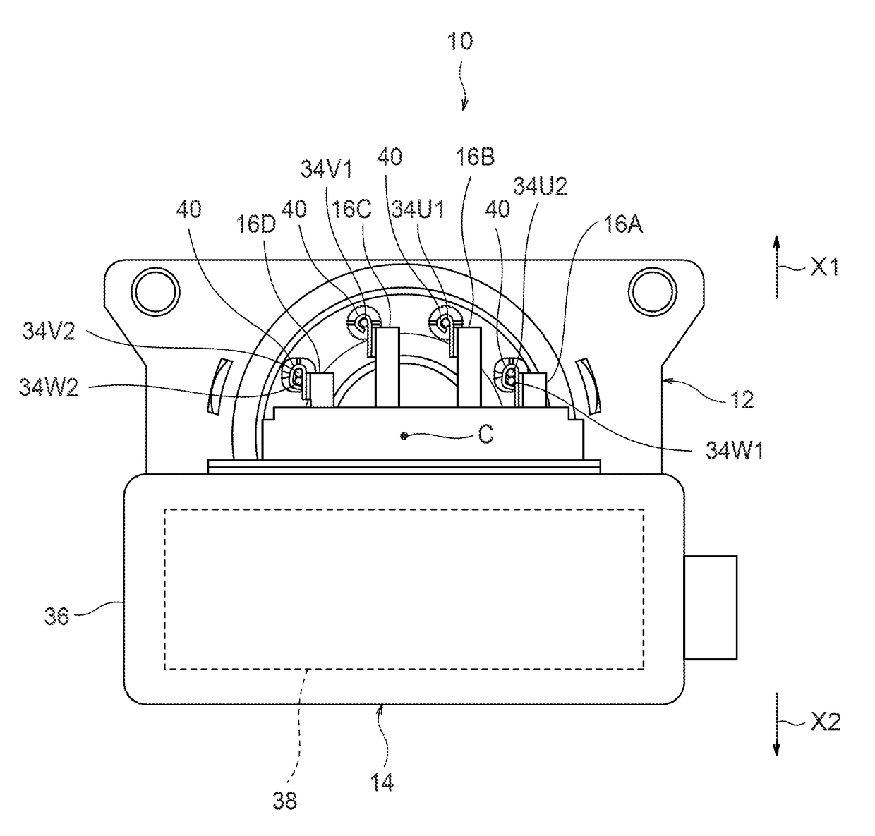
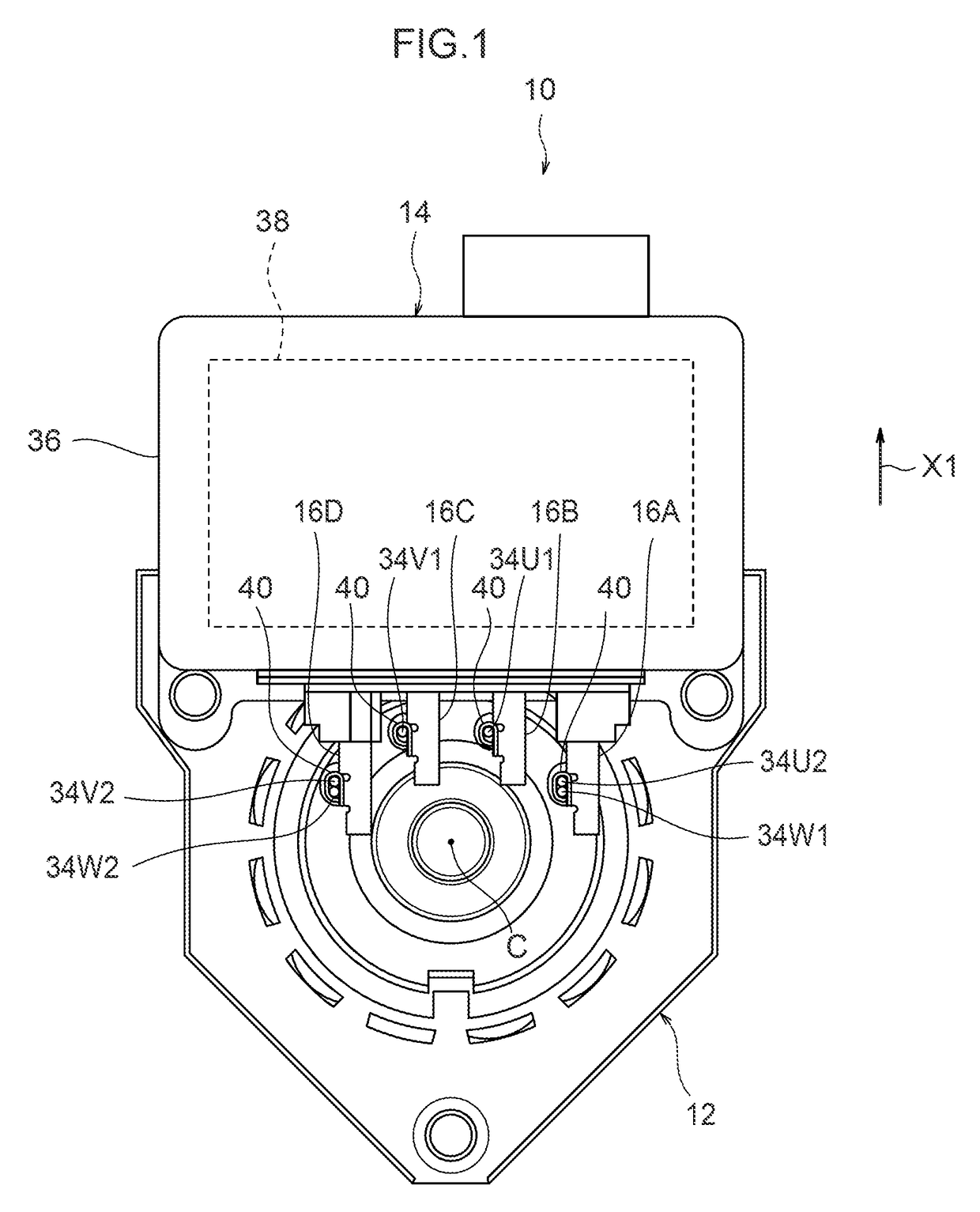
[0050]As illustrated in FIG. 1, a rotating electrical device 10 according to the exemplary embodiment of the present invention is equipped with a motor section 12, a circuit section 14 and plural terminals 16A to 16D.

[0051]The motor section 12 is, for example, a 10-pole, 12-slot outer-rotor brushless motor. As illustrated in FIG. 5A and FIG. 5B, the motor section 12 includes a rotor 18 and a stator 20

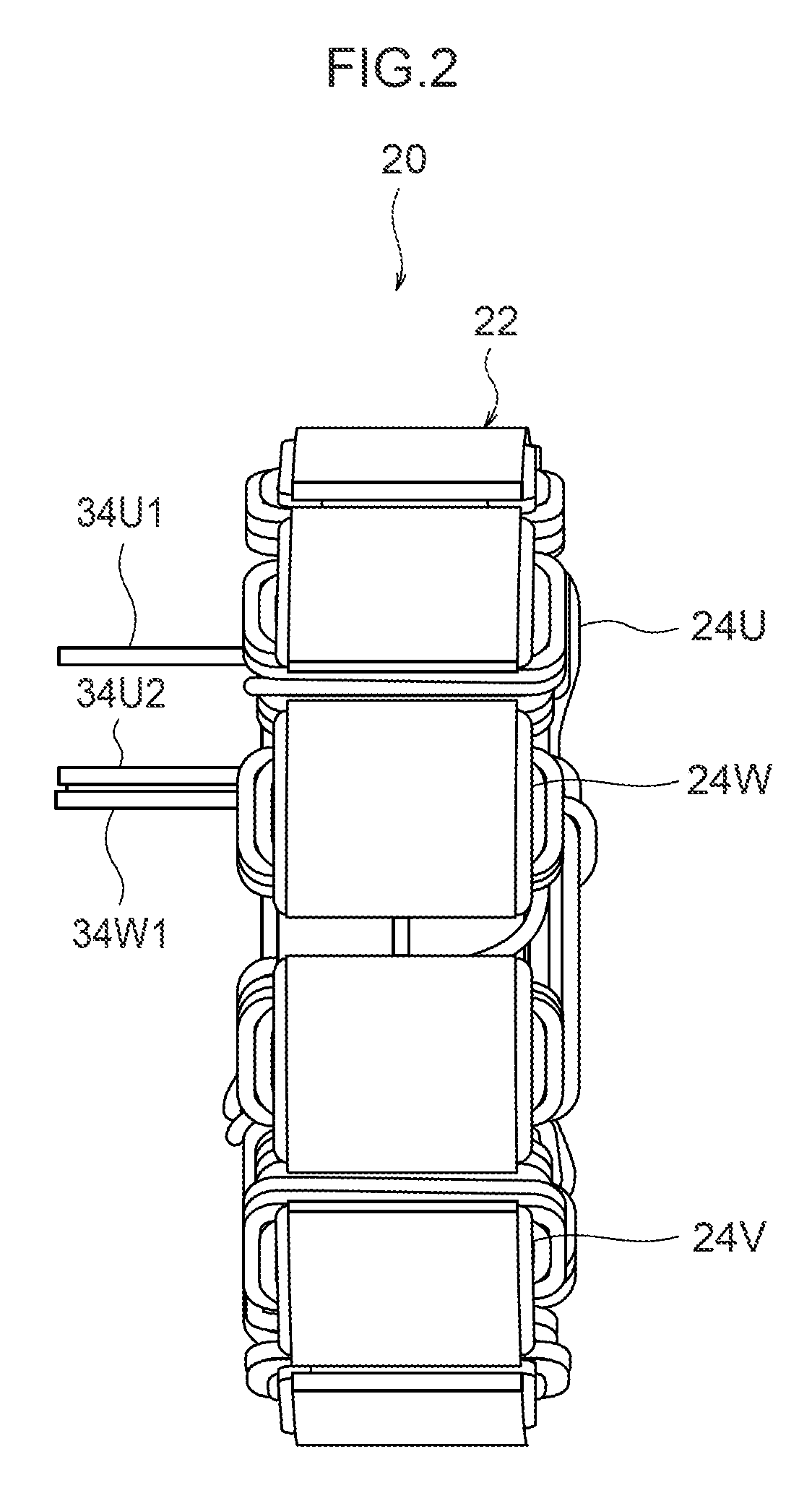
[0052]The stator 20 includes a stator core 22 and plural windings 24U, 24V, 24W. The stator core 22 includes a core main body 26 formed of plural layered core sheets, and an insulator 28 installed to the core main body 26 from both sides in an axial direction of the motor section 12. A ring shaped circular ring portion 30 is formed to an inner peripheral side of the stator core 22, and plural teeth 32U1 to 32W4 are formed in a radial shape at the periphery of the circular...


PUM


Abstract

A rotating electrical device comprising a circuit section being disposed offset from a motor section to one side or another side, in a direction orthogonal to an axial direction of the motor section as viewed in the axial direction of the motor section; a stator configuring the motor section together with a rotor, the stator comprising a plurality of teeth formed in a radial shape and a plurality of windings that each includes a terminal-end portion that extends in the axial direction of the motor section, the plurality of windings being respectively wound on any of the plurality of teeth such that each of the terminal-end portions is disposed further to a side in the orthogonal direction from a central axis of the motor section where the circuit section is disposed; and a plurality of terminals that wire-in the circuit section and the terminal-end portions of the plurality of windings.

Description

CROSS-REFERENCE TO RELATED APPLICATION[0001]This application claims priority under 35 USC 119 from Japanese Patent Application, No. 2013-102508 filed May 14, 2013, the disclosure of which is incorporated by reference herein.BACKGROUND OF THE INVENTION[0002]Technical Field[0003]The present invention relates to a rotating electrical device.[0004]Related Art[0005]As illustrated in Japanese Patent Application Laid-Open (JP-A) No. 2010-273450 (FIG. 12), rotating electrical devices exist that are provided with a motor section including a rotor and a stator, and with a circuit section disposed, with respect to the motor section, offset to one side in a direction orthogonal to an axial direction of the motor section, as viewed in the motor section axial direction.[0006]In such a rotating electrical device, the stator includes plural teeth formed in a radial shape, and plural windings wound on the plural teeth. Terminal-end portions of the plural windings extend in the axial direction of the...

Claims


Application Information

Patent Timeline
Patent Type & Authority Patents(United States)
IPC IPC(8): H02K11/00H02K3/00H02K3/28
CPCH02K3/28
Inventor SAHARA, YOSHIMICHIOOISHI, MASATO
Owner DENSO CORP
Learn More