Electrical connector with differing channel and signal terminal structures
- Summary
- Abstract
- Description
- Claims
- Application Information
AI Technical Summary
Benefits of technology
Problems solved by technology
Method used
Image
Examples
Embodiment Construction
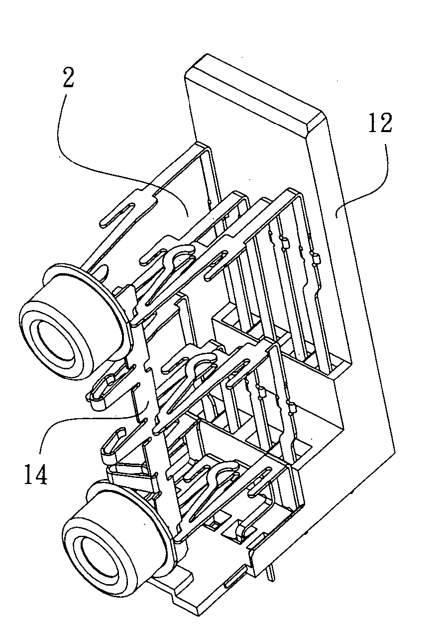
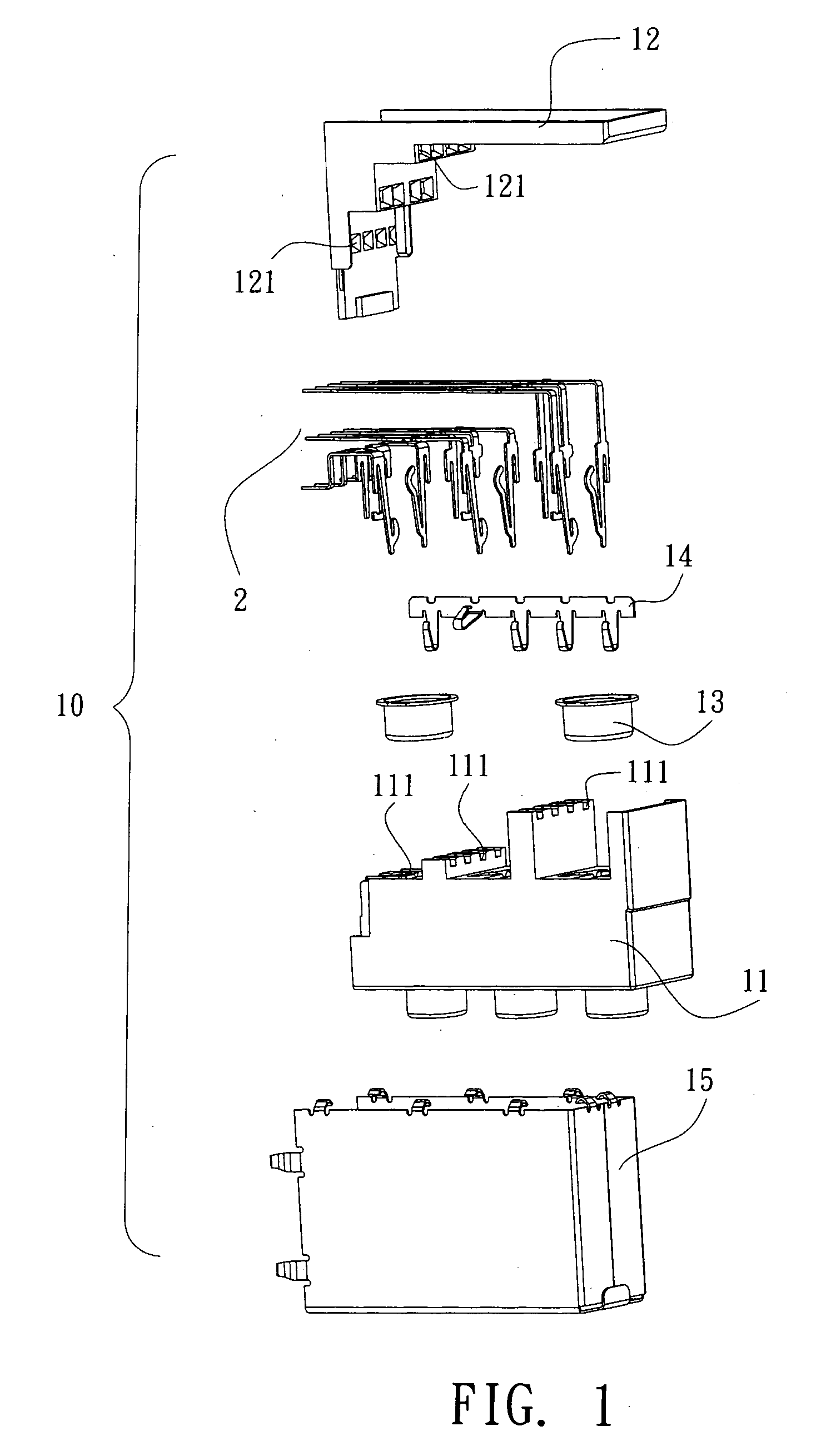
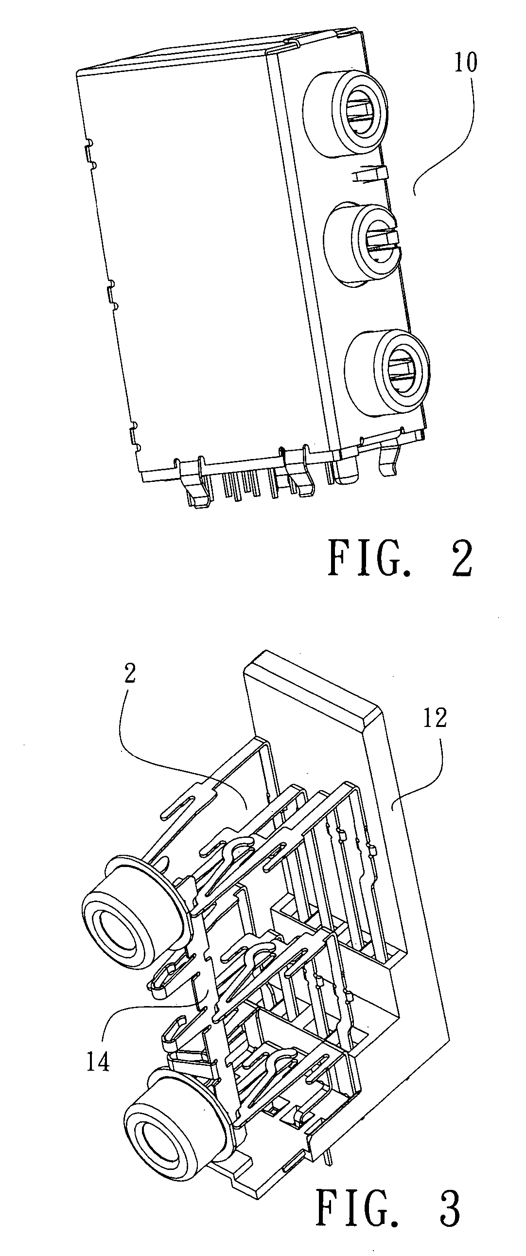
[0019] Referring to FIGS. 1 to 7, an electrical connector according to the present invention 10 comprises a body 11, a rear base 12, a ring 13, three rows (top, middle, and bottom) of channel terminal and signal terminal 2, a ground terminal 14, and a shield housing 15 mounted on the exterior of the body 11 and the rear base 12, wherein the rear end plane of the body 11 is provided with a receiving chamber 111 to receive the top, middle, and bottom rows of terminals; the rear base 12 is also provided with three rows of corresponding terminal receiving holes 121, and the ground terminal 14 is received in the body 11 and in contact with the channel terminal and signal terminal 2 and the ring 13, respectively.
[0020] As shown in FIGS. 5 to 7, the channel terminal and signal terminal 2 is integratedly formed on the terminal blanks. The top row of channel terminal and signal terminal 21, for example, is integratedly formed on the terminal blank 31; The middle row of channel terminal and ...
PUM
 Abstract
Description
Claims
Application Information
 - R&D
- Intellectual Property
- Life Sciences
- Materials
- Tech Scout
- Unparalleled Data Quality
- Higher Quality Content
- 60% Fewer Hallucinations
Browse by: Latest US Patents, China's latest patents, Technical Efficacy Thesaurus, Application Domain, Technology Topic, Popular Technical Reports.
© 2025 PatSnap. All rights reserved.Legal|Privacy policy|Modern Slavery Act Transparency Statement|Sitemap|About US| Contact US: help@patsnap.com


