Tire winch, tire winch kit and method

a technology of tire winches and kits, applied in the field of pulling devices, can solve the problems of vehicles moving a shorter distance, and achieve the effect of quick deploymen

Inactive Publication Date: 2006-03-07
VAN COR DALE E
View PDF23 Cites 6 Cited by
  • Summary
  • Abstract
  • Description
  • Claims
  • Application Information

AI Technical Summary

Benefits of technology

[0025]It is a further aspect of the present invention to provide an apparatus, system and kit for pulling a vehicle a relatively short distance that may be quickly deployed.
[0026]It is a further aspect of the present invention to provide an apparatus, system and kit for pulling a vehicle a relatively short distance that may be effectively used by all drivers of heavy or light vehicles.
[0027]It is a further aspect of the present invention to provide an apparatus, system and kit for pulling a vehicle a relatively short distance that is readily adapted to provide a mechanical advantage in towing applications.
[0028]It is a further aspect of the present invention to provide an apparatus, system and kit for pulling a vehicle a relatively short distance that provides at least one safety mechanism that prevents excessive force from being exerted upon the system.
[0029]It is a further aspect of the present invention to provide a method for pulling an object a relatively short distance that provides a mechanical advantage over direct-pull methods.
[0030]It is a still further aspect of the present invention to provide a method for pulling an object a relatively short distance that is safer than other known methods.

Problems solved by technology

However, because the circumference of the spool is less than the circumference of the tire, the cable will unwind at a slower rate than the vehicle is moving forward, creating a pulling force on the stranded vehicle that causes the vehicle to move a shorter distance than is traveled by the towing vehicle.
However, in others, the torque limiting means uses a frictional engagement between the spool and attachment means that will break free and rotate when the maximum pre-set torque is reached.

Method used


Image

  • Tire winch, tire winch kit and method
  • Tire winch, tire winch kit and method
  • Tire winch, tire winch kit and method

Examples


Embodiment Construction

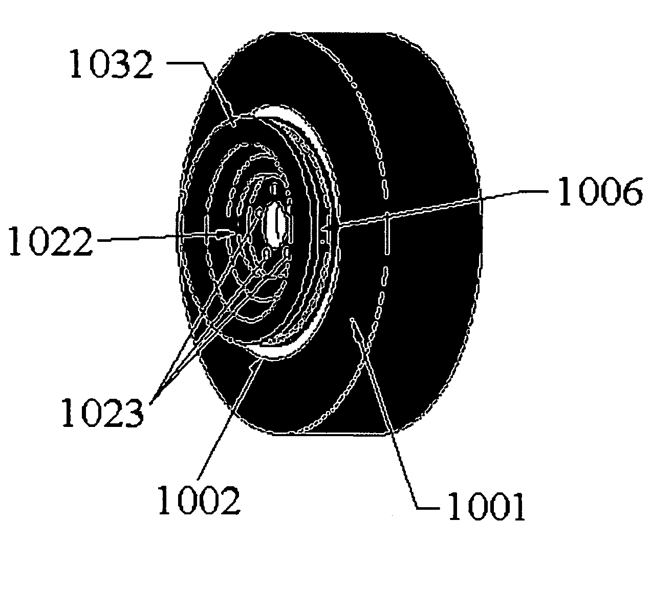
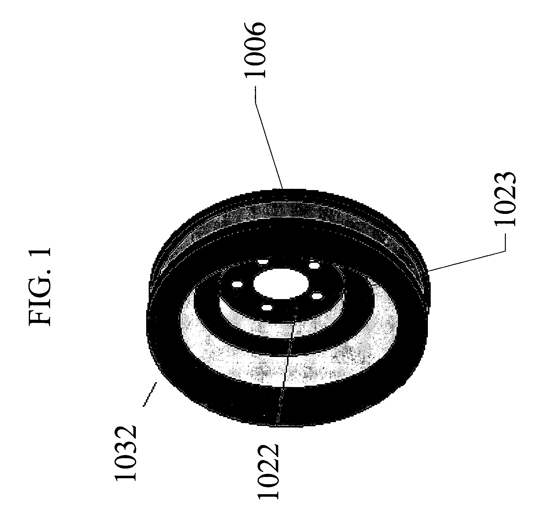
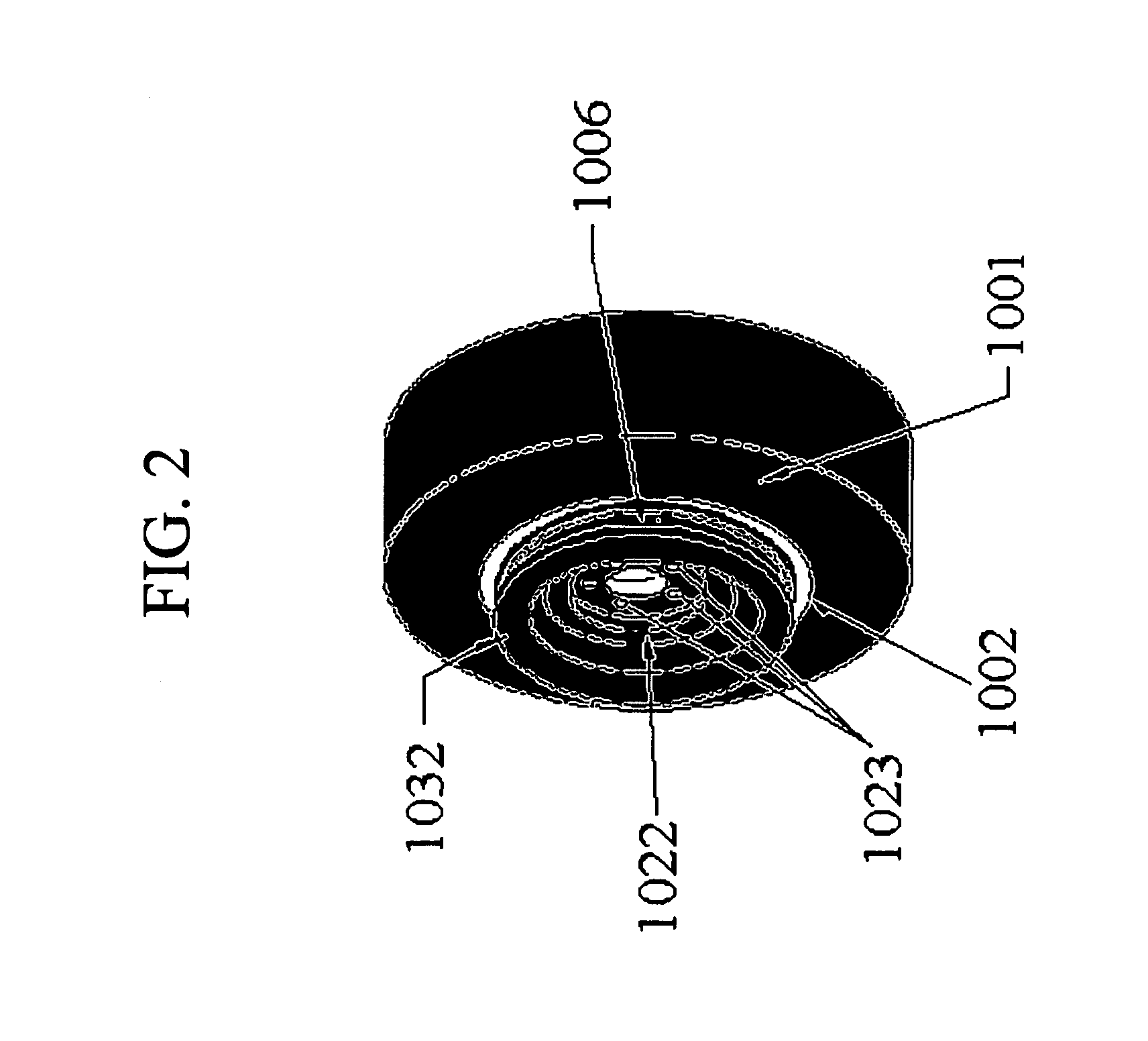
[0056]Referring first to FIGS. 1 and 2, one embodiment of a hub-mounted spool 1032 is shown. The hub-mounted spool 1032 includes a substantially cylindrical outer hub 1006 that is dimensioned to accept and wind a cable thereabout. A central portion 1022 is dimensioned to fit over the rim 1002 of a tire 1001 and includes a plurality of holes 1023 therethrough that are dimensioned and positioned to mate with lug bolts (not shown) that extend from the wheel of the vehicle (not shown). In this embodiment, the central portion 1022 and holes 1023 serve as the means for attaching the spool 1032 to a tire 1001 such that the rotation of the tire 1001 causes the spool 1032 to rotate. However, this means may take many forms. For example, in some embodiments, this means is one of the toothed means described below in connection with the quick connecting versions of the system. In others, only two holes are provided, allowing the spool to be attached without removing all lug nuts. In still others...


PUM


Abstract

A tire winch, tire winch kit, and method of pulling an object. The tire winch includes a spool having a substantially cylindrical hub dimensioned to accept and wind a cable thereabout, and a means for attaching the spool to a tire such that the rotation of the tire causes the spool to rotate. The kit includes a winding spool, an unwinding spool and a means for attaching one of the spools to the tire. The method includes the steps of attaching the winch to a drive wheel of a vehicle, winding a flexible member around the hub of the winch, attaching the free end of the member to an object, and driving away from the object to unwind the member from the winch and, thereby, pull the object a distance that is less than the distance traveled by the vehicle.

Description

CLAIM OF PRIORITY[0001]This application claims the benefit of priority of U.S. Provisional Patent Application Ser. No. 60 / 422,171 filed on Oct. 29, 2002.FIELD OF THE INVENTION[0002]The present invention relates to the field of pulling devices and, in particular, to tire winches, tire winch kits and methods for pulling an object a relatively short distance using a vehicle.BACKGROUND OF THE INVENTION[0003]It is commonplace for an automobile, truck, and other wheeled vehicle to leave a paved roadway and lose tire traction, resulting in spinning wheels that leave the vehicle immovable under its own power. In cases where the vehicle is relatively light and has multiple occupants, it is often possible for the passengers to push the vehicle a short distance, allowing the wheels to regain traction. However, lone drivers, or those with relatively heavy vehicles, are typically not able to move the vehicle even the short distance that is required to regain traction. Drivers stuck in this predi...

Claims


Application Information

Patent Timeline
Patent Type & Authority Patents(United States)
IPC IPC(8): B66D1/00
CPCB66D1/005
Inventor VAN COR, DALE E.
Owner VAN COR DALE E
Why Eureka
Try Eureka