
Pediatric intramedullary nail and method

Inactive Publication Date: 2006-03-07
PHILLIPS JONATHAN
View PDF27 Cites 111 Cited by
  • Summary
  • Abstract
  • Description
  • Claims
  • Application Information

AI Technical Summary

Benefits of technology

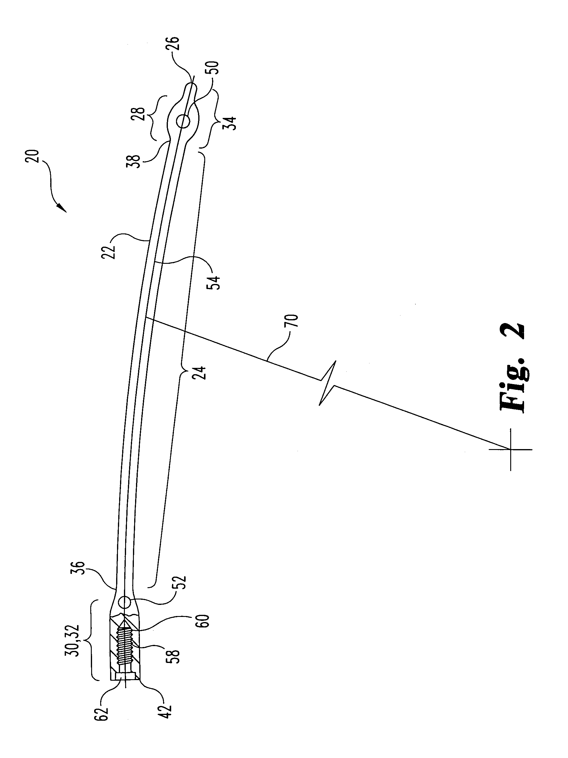
[0009]In one general aspect, the present invention provides an intramedullary nail for insertion within an intramedullary canal of a long bone and fixing a fracture in the long bone. The nail is especially suitable for adolescent or preadolescent aged children, however, the nail may be useful in other orthopedic applications as well. The nail generally comprises an elongate member having a longitudinal axis, a proximal end section, a distal end section and a solid central section extending between the proximal and distal end sections. The proximal and distal end sections respectively have fastener receiving areas of greater cross sectional dimensions than the central section. The fastener receiving areas each include at least one hole extending transverse to the longitudinal axis of the elongate member for receiving a cross fastener adapted to secure to the bone on opposite sides of the elongate member. The proximal and distal end sections provide rigid anchoring locations relative to the central section and the central section provides flexibility to promote healing of the fracture.
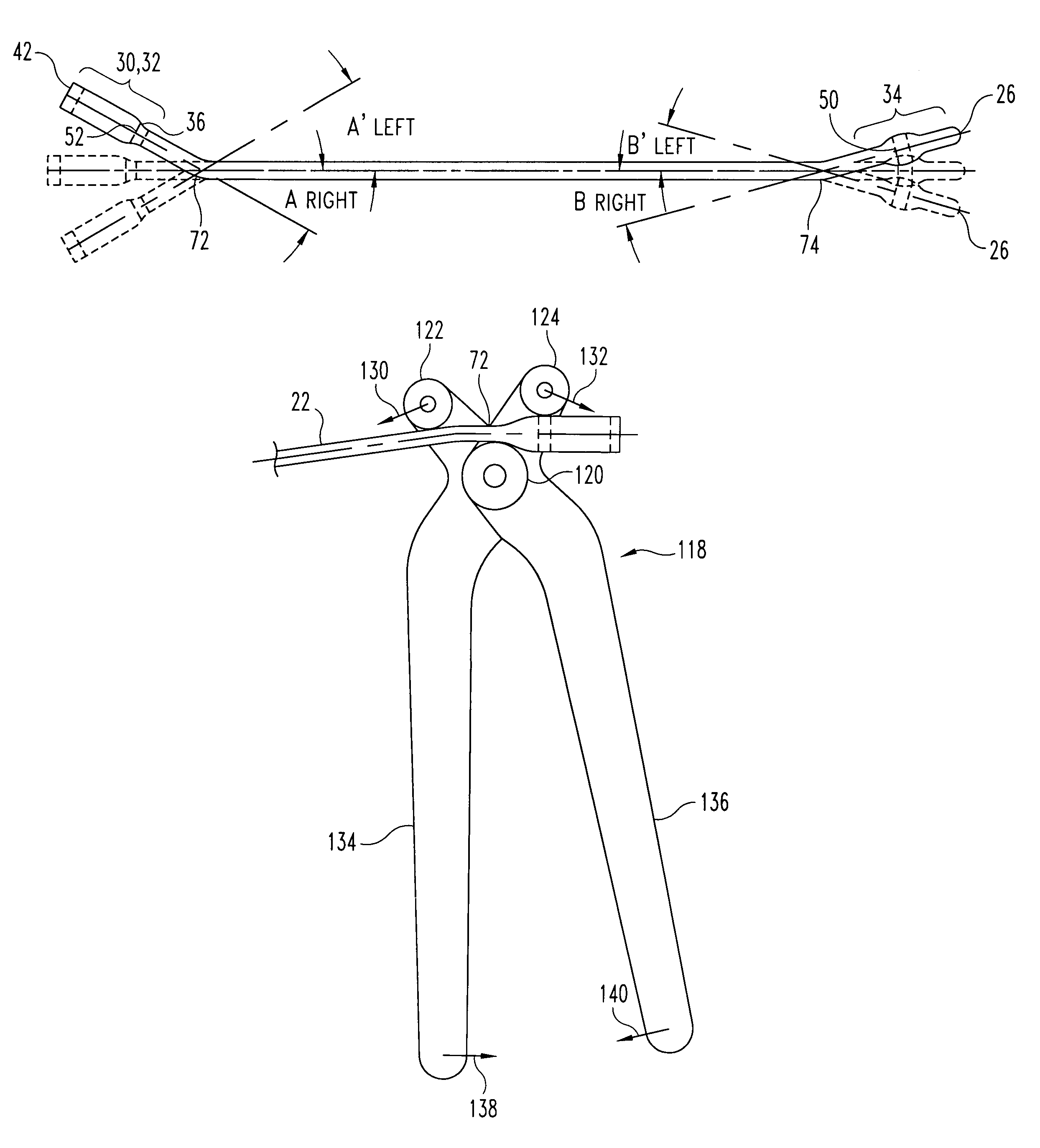
[0010]In the preferred embodiment, the central section of the elongate member is curved in the sagital plane to generally follow the curvature of a femur. The proximal and distal end sections are bent out of this plane and form acute angles with respect to the sagital plane. The proximal and distal end sections are each bent laterally to one side of the central section. The side to which the proximal and distal end sections are bent depends on whether the nail will be used in a right or left femur and also allows easier insertions across the fracture. The bend of the distal end section allows for easier insertion of the nail from an insertion point extending through the greater trochanter of the femur. The bend of the proximal end section ensures that the proximal tip is presented directly at the insertion point after fixation so that it may be easily accessed for removal purposes upon healing of the bone.
[0012]The bone nail and method of this invention allow the surgeon to better avoid the critical arterial blood supply to the femoral head which crosses at the piriformis fossa, i.e., the traditional point of entry for an adult nail. Instead the entry point is on the greater trochanter, a location distinctly lateral of the critical region of the piriformis fossa. The very vulnerable growth plate between the greater trochanter and the femoral neck is also avoided using the nail and entry point in accordance with this invention. Another unique feature of the invention is the ability of the bone nail to be flexible, yet custom bent to match the exact geometry of the proximal femur, while also allowing interlocking with cross fasteners. In general, the preferred inventive nail provides interlockability, a relatively small solid cross section to provide flexure along at least the majority of the length of the nail, and malleability to allow custom bending especially at the proximal end.

Problems solved by technology

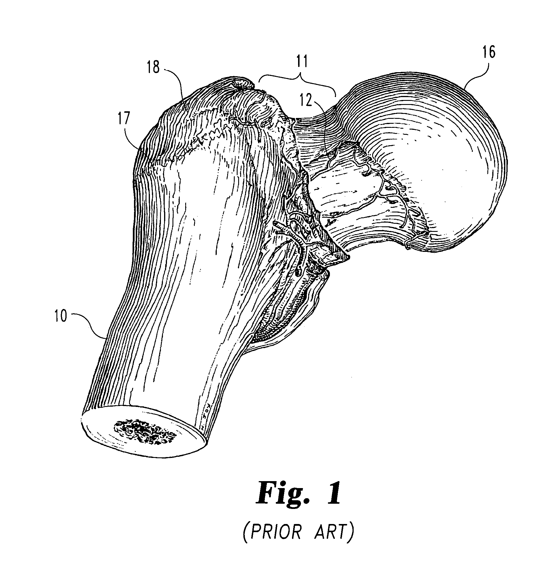
Referring to FIG. 1, a special problem in pediatric orthopedics exists in that reaming through the typical entry point in a femur 10, i.e., the piriformis fossa 11, can be to dangerous for the child.
If this artery 12 is damaged during the fixation procedure, such as while the intramedullary canal is being reamed to accept a nail, or possibly during insertion or after insertion of the nail, various complications can result.
Currently available interlocked nails can be inserted away from the lateral epiphyseal artery 12 but are so rigid that they migrate during insertion dangerously close to the artery 12 and can endanger it.
In addition, the large proximal size of small adult interlocked nails, which have typically been used in children, increases the potential for damage to the growth plate 17 at the proximal femur.
Among possible solutions, retrograde nailing avoids the proximal femur but also has at least one potential problem.
However, spiral or comminuted fractures often need additional external support, such as with a cast or brace.
This is due to the inability of the non-interlocked nail to effectively, prevent rotation or length compromise at the fracture.

Method used


Image

  • Pediatric intramedullary nail and method
  • Pediatric intramedullary nail and method
  • Pediatric intramedullary nail and method

Examples


Embodiment Construction

[0029]An exemplary intramedullary nail 20, as illustrated in FIGS. 2–4, comprises an elongate member 22. In an embodiment intended for use in a femur of a child or adolescent, typically ages 6–14, for example, the nail 20 is formed from titanium and has a generally cylindrical shape with a diameter along a solid central section 24 of between 4 mm and 7 mm, although this is not intended as a limitation. Central section 24 should have a certain amount of elastic flexibility to permit accurate placement within the femoral canal as discussed below. Such elastic flexibility, which permits some flexure during movement and weight bearing activity, confers an additional benefit in that it has been found to stimulate bone healing. The nail 20 preferably ends in a rounded, smooth and tapered distal tip 26.

[0030]The nail 20 has two widened sections or fastener receiving areas 28, 30 in respective proximal and distal end sections 32, 34. Each fastener receiving area 28, 30 is formed with an inc...


PUM


Abstract

An intramedullary nail (20) and related method for fixing a fracture in a long bone. The nail (20) comprises an elongate member (22) having a longitudinal axis (54), a proximal end section (32), a distal end section (34) and a solid central section (24) extending between the proximal and distal end sections (32, 34). The proximal and distal end sections (32, 34) respectively include proximal and distal fastener receiving areas (28, 30) of greater cross sectional dimensions than the central section (24). Each fastener receiving area (28, 30) includes at least one hole (50, 52) extending transverse to the longitudinal axis for receiving a cross fastener (110) adapted to secure to the bone on opposite sides of the elongate member (22). The proximal and distal end sections (32, 34) thereby provide rigid anchoring locations relative to the central section (24) and the central section provides flexibility to promote healing of the fracture.

Description

CROSS-REFERENCE TO RELATED APPLICATIONS[0001]The present application claims the benefit of U.S. Provisional Patent Application No. 60 / 252,536 filed 22 Nov. 2000, the disclosure of which is entirely incorporated by reference herein, and which is a continuation-in-part of International Patent Application No. PCT / US00 / 14840 filed 26 May 2000 and published in the English language 7 Dec. 2000, the disclosure of which is entirely incorporated by reference herein, and which is a continuation in part of U.S. patent application Ser. No. 09 / 321,369 filed 27 May 1999, now abandoned the disclosure of which is entirely incorporated by reference herein.BACKGROUND OF THE INVENTION[0002]1. Field of the Invention[0003]The present invention relates to devices and methods for repairing bone fractures, and, more particularly, to intramedullary nails and related internal fixation methods especially suitable for repairing long-bone fractures in children.[0004]2. Description of Related Art[0005]The use of...

Claims


Application Information

Patent Timeline
IPC IPC(8): A61B17/56A61B17/17A61B17/72A61B17/86A61B17/88A61B17/92
CPCA61B17/7208A61B17/8863A61B17/1725A61B17/921A61B17/863
Inventor PHILLIPS, JONATHAN
Owner PHILLIPS JONATHAN
Learn More