Strandboard molding having holes at angles of 20 degrees to vertical or more

a technology of strandboard molding and angles, which is applied in the direction of cutting tools, matches, saw chains, etc., can solve the problems of difficult to push the punch through the compressed mat, become more difficult to form such holes, and complicate the mold

a technology of strandboard molding and angles, which is applied in the direction of cutting tools, matches, saw chains, etc., can solve the problems of difficult to push the punch through the compressed mat, become more difficult to form such holes, and complicate the mold

US7008684B2Inactive Publication Date: 2006-03-07GFP STRANDWOOD

Image

  • Strandboard molding having holes at angles of 20 degrees to vertical or more
  • Strandboard molding having holes at angles of 20 degrees to vertical or more
  • Strandboard molding having holes at angles of 20 degrees to vertical or more

Examples


Embodiment Construction

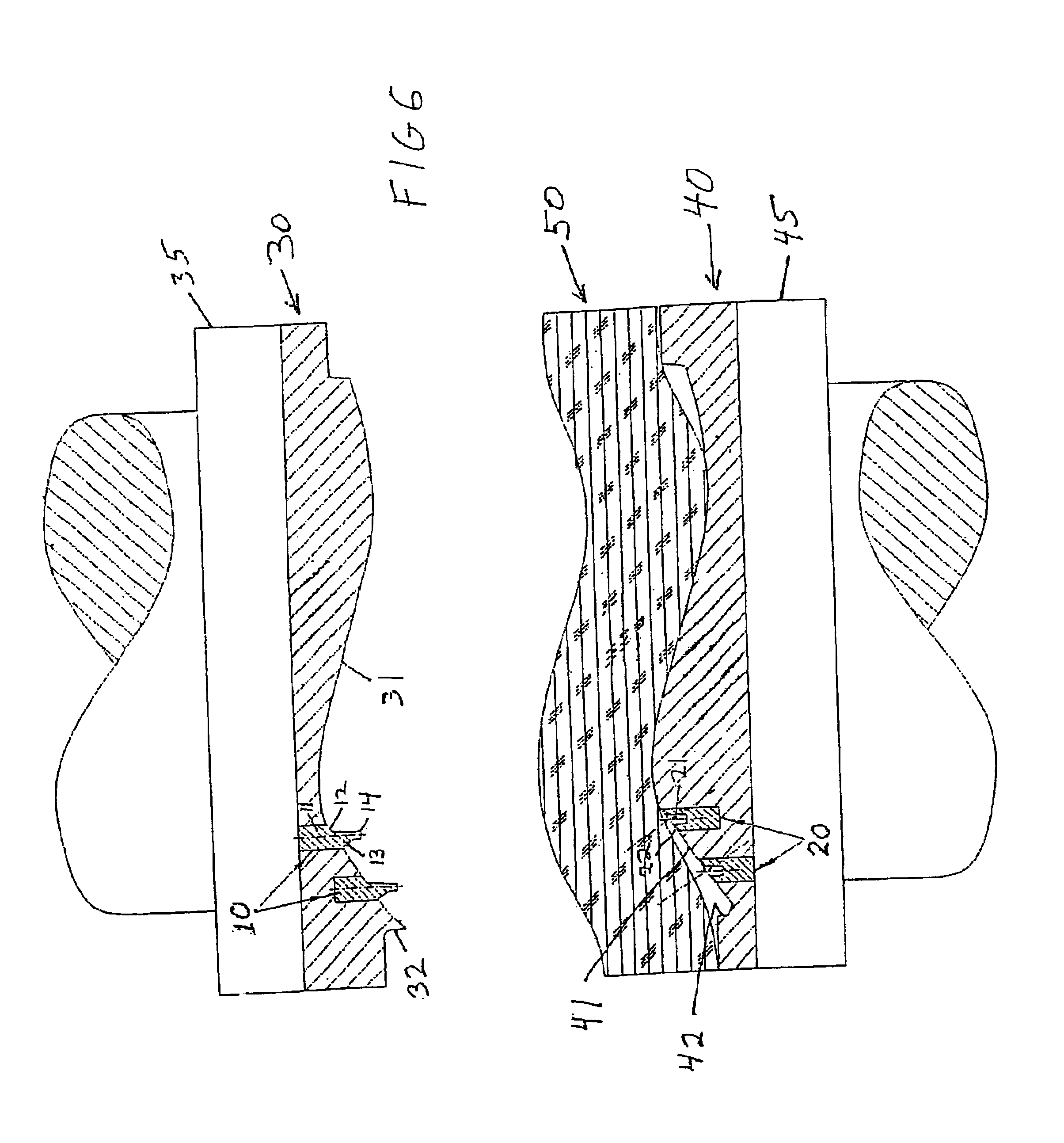
[0026]In the preferred embodiment, punches 10 and punch receiving inserts 20 are located in the upper and lower mold halves 30 and 40, respectively (FIG. 6). A loosely felted mat 50 of wood flakes is positioned on lower mold 40 (FIG. 6). When mold parts 30 and 40 are brought together to apply heat and pressure to mat 50, it is compressed and cured into an article of manufacture 50′, having holes formed therein by punches 10 passing through mat 50 and forcing wood flakes down into punch receiving inserts 20.

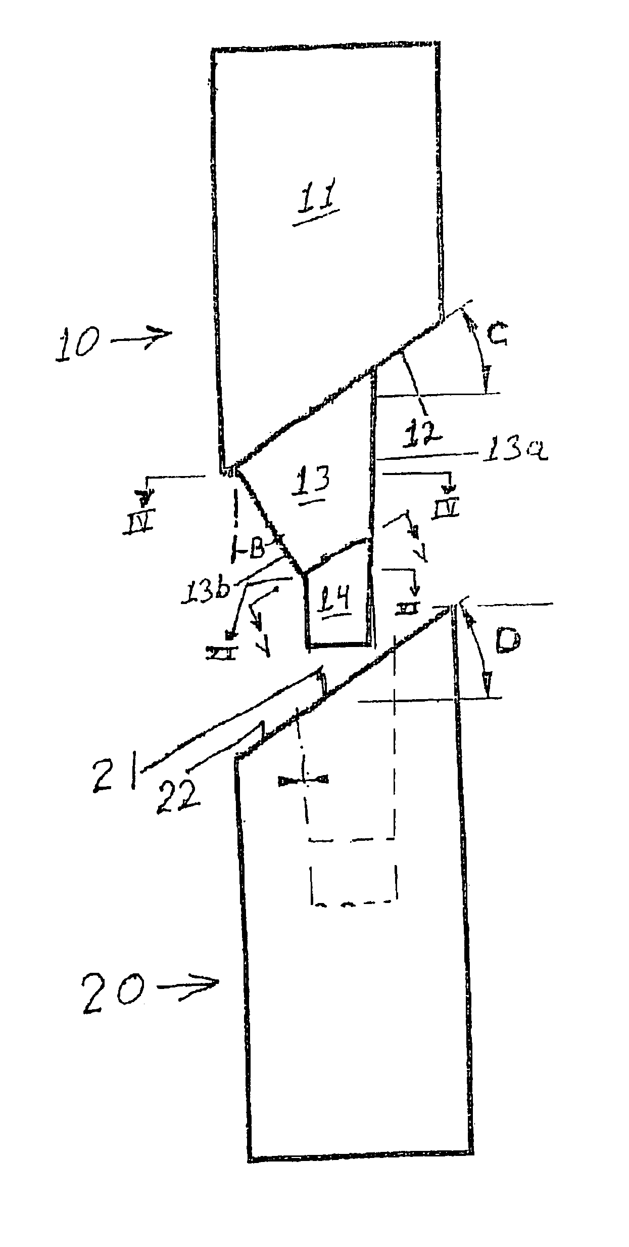
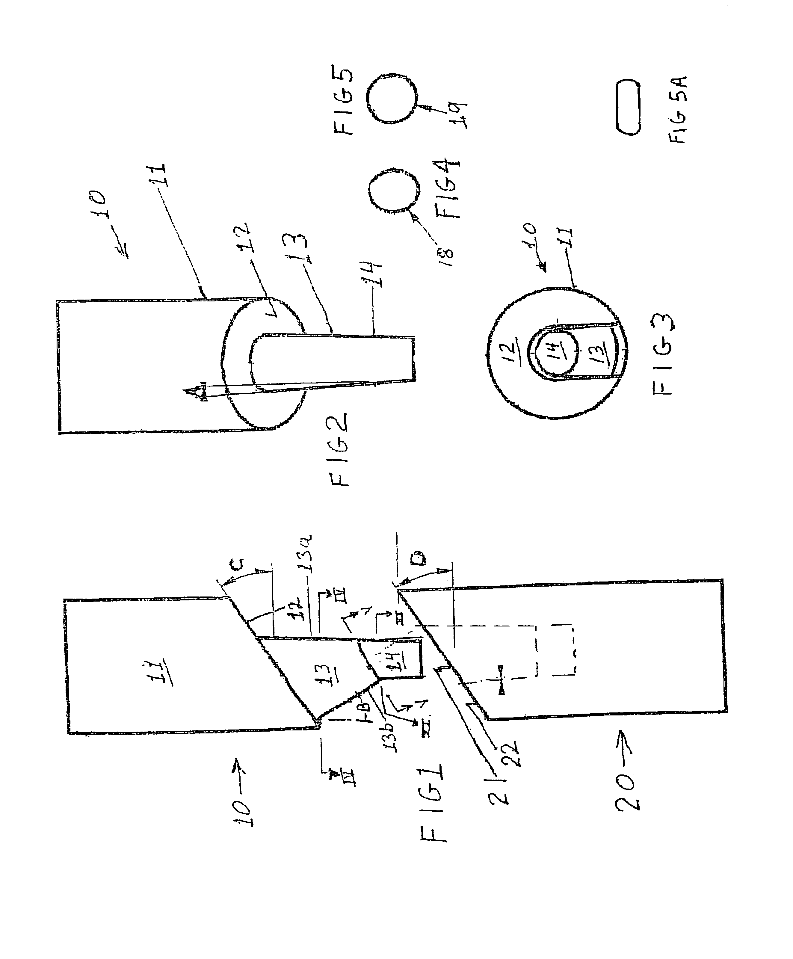
[0027]Each punch 10 comprises a base 11 having a base face 12 (FIGS. 1, 2). Base 11 is inserted into a receiving socket in upper mold half 30, as for example by threading into the socket. Base face 12 is then generally aligned with the cavity defining surface 31 of upper mold 30 (FIG. 6).

[0028]The lopsided funnel-shaped, hole defining portion 13 of punch 10 projects downwardly from base face 12 (FIGS. 1, 2). Hole defining portion 13 is defined as being a lopsided funnel in configu...


PUM

PropertyMeasurementUnit
angleaaaaaaaaaa
angleaaaaaaaaaa
lengthaaaaaaaaaa

Abstract

Mold apparatus for molded wood strand three-dimensionally carved articles of manufacture using at least one hole punch comprised of a base and a funnel shaped hole-defining portion having a funnel angle of 20 degrees or greater to vertical for producing molded holes at angles of 20 degrees or greater to vertical, to facilitate insertion of items such as a T nut within the molded hole in an assembly-line like fashion.

Description

CROSS-REFERENCE TO RELATED APPLICATION[0001]The present application is a divisional of U.S. application Ser. No. 09 / 847,259, filed on May 2, 2001, entitled STRANDBOARD MOLDING HAVING HOLES AT ANGLES OF 20 DEGREES TO VERTICAL OR MORE, now U.S. Pat. No. 6,592,792, which claims priority to Provisional Patent Application No. 60 / 201,350, filed on May 2, 2000 entitled STRANDBOARD MOLDING HAVING HOLES AT ANGLES OF 20 DEGREES TO VERTICAL OR MORE.BACKGROUND OF THE INVENTION[0002]A. Field of the Invention[0003]The present invention relates to the revolutionary wood flake molding technology invented by wood scientists at Michigan Technological University during the latter part of the 1970s.[0004]B. Background of the Art[0005]Wood flake molding, also referred to as wood strand molding, is a technique for molding three-dimensionally configured objects out of binder coated wood flakes having an average length of about 1¼ to about 6 inches, preferably about 2 to about 3 inches; an average thicknes...

Claims


Application Information

Patent Timeline
07 Mar 2006
Publication
US7008684B2
IPC
B32B5/12; B27N3/18; B29C43/40
CPC
B29C43/40; B29C2793/0018; B29K2105/0854; B29K2105/0863; Y10T428/139; B29K2311/14; Y10T428/24298; Y10T428/24066
Inventors
HAATAJA, BRUCE A.