
Integrated locking device

a locking device and locking device technology, applied in the direction of instruments, machine supports, electrical apparatus casings/cabinets/drawers, etc., can solve the problems of inconvenient removal operation of removable devices, inability to install all peripheral devices therein, and inability to effectively lock an electrical apparatus, etc., to achieve the effect of convenient peripheral devices, effective locking of electrical apparatuses, and effective removal of removable devices

Active Publication Date: 2006-03-07
QUANTA COMPUTER INC
View PDF7 Cites 34 Cited by
  • Summary
  • Abstract
  • Description
  • Claims
  • Application Information

AI Technical Summary

Benefits of technology

Enables safe and convenient one-handed removal of peripheral devices, reducing the overall space occupied by the locking mechanism and preventing interference with other components, thus enhancing the portability and operability of notebook computers.

Problems solved by technology

However, a common problem of the notebook computer is that the interior space is too small to install all peripheral devices therein.
Accordingly, the locking device and the withdrawal mechanism occupy a quite large area and space in the notebook computer and the removable device has to be released from the notebook computer with both hands of the user.
The removal operation of the removable device is not convenient.
Therefore, in the perpendicular direction, the locking device and the latch have to work a quite long distance for locking and releasing the removable device safely.
However, the interior space of a notebook computer is increasingly tight, and the locking device with a long protruding distance from the removable device easily interferes with other devices.

Method used


Image

  • Integrated locking device
  • Integrated locking device
  • Integrated locking device

Examples


Embodiment Construction

[0022]The following description is of the best presently contemplated mode of carrying out the present invention. This description is not to be taken in a limiting sense but is made merely for the purpose of describing the general principles of the invention. The scope of the invention should be determined by referencing the appended claims.

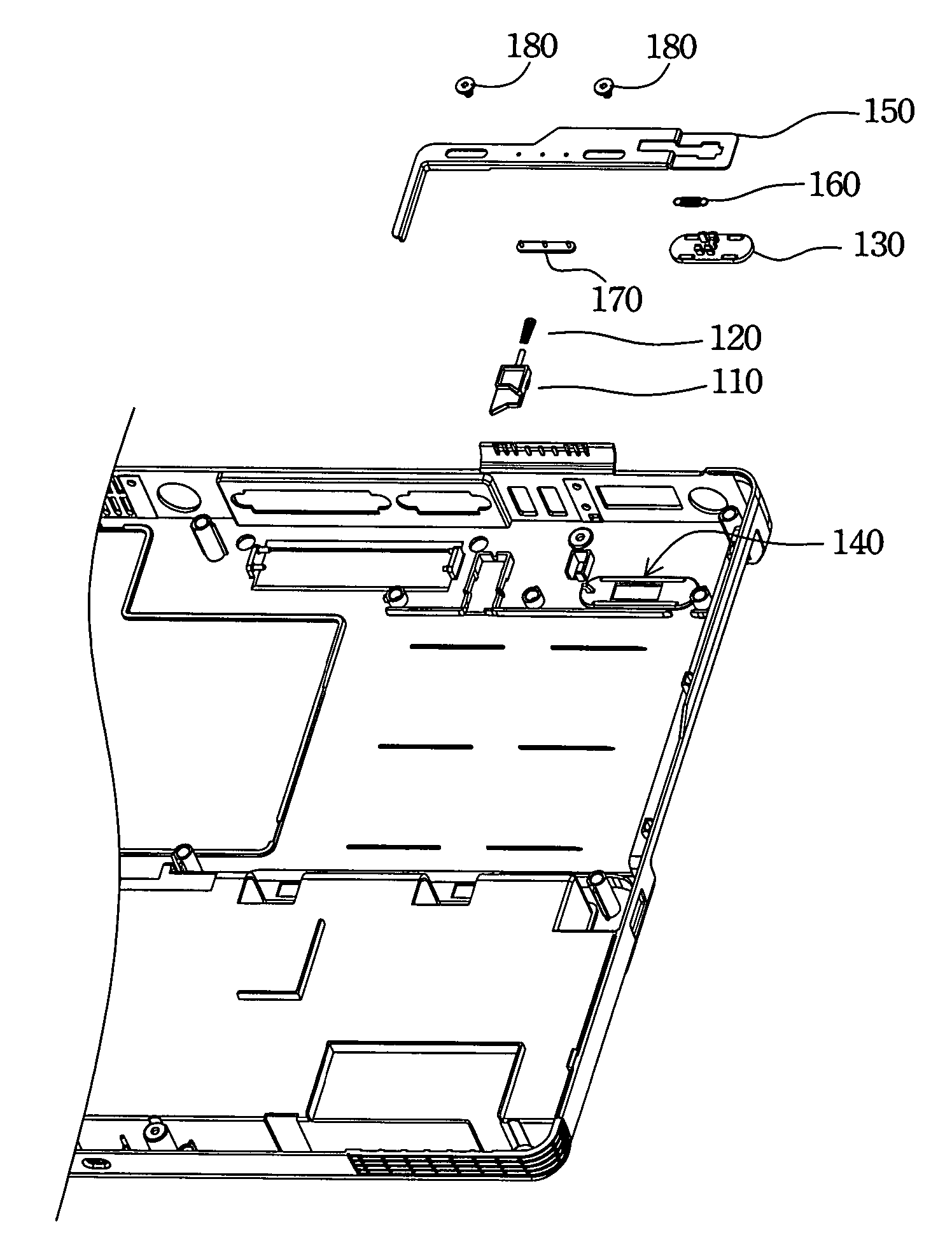
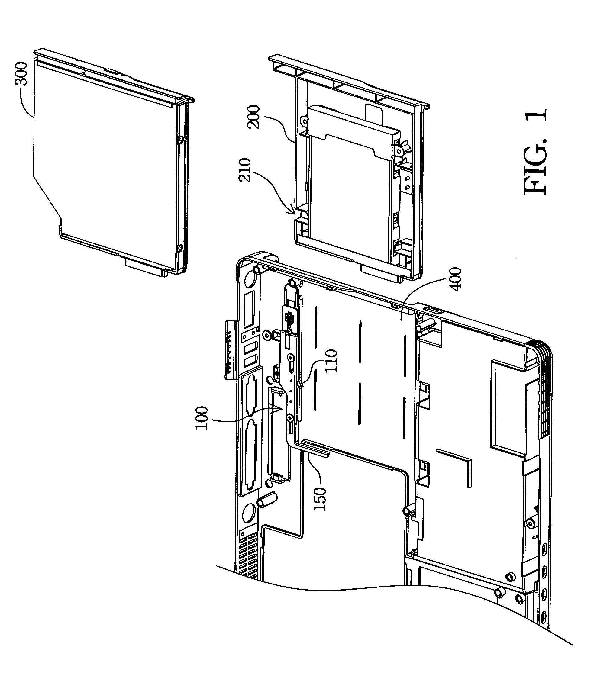
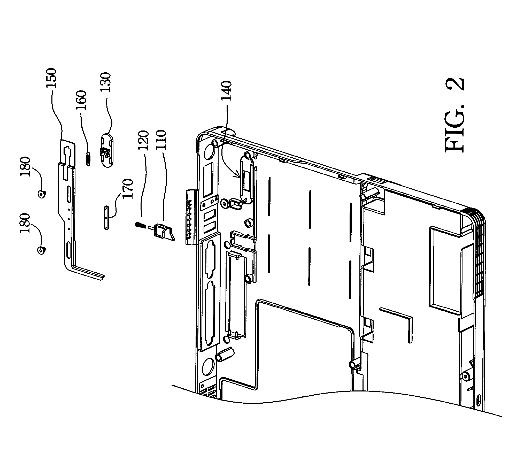
[0023]FIG. 1 is a schematic view of a preferred embodiment of an integrated locking device according to the present invention. An integrated locking device 100 is configured in a notebook computer, and the integrated locking device 100 utilizes a latch 110 to fix a first removable device 200 or a second removable device 300 in a fixing container 400. The first removable device 200 is a peripheral device and the second removable device 300 is another peripheral device for the notebook computer. The peripheral device includes, for example, a removable hard disk, a removable floppy disk drive, a spare battery module, or an optical disk drive of the ...


PUM


Abstract

An integrated locking device is described. The integrated locking device is utilized to lock and remove a removable device and is especially suitable in a notebook computer. The locking device has a latch, a first elastic device, a push arm, and a sliding switch. The latch locks a fixing indention of the removable device to fix the removable device. The first elastic device provides a force to push the latch moving forward and a space for the latch moving back. When the removable device is taken out, the sliding switch pushes the push arm first. Then, a slider of the push arm pushes a sliding inclined surface of the latch to withdraw the latch from the fixing indention. Subsequently, the push arm pushes the removable device outward for releasing the removable device. The movements of the sliding switch and the latch form an included angle, preferably about 90 degrees.

Description

FIELD OF THE INVENTION[0001]The present invention relates to an integrated locking device, and more particularly, to an integrated locking device for locking a peripheral device in a notebook computer.BACKGROUND OF THE INVENTION[0002]Information technology and the computer industry are highly developed now. Portable electronic devices, such as a notebook computer, are widely used. Due to weight and practical requirements, portable devices tend to be lighter, thinner and smaller. The notebook computer is a successful product because the notebook computer with powerful calculation capability deals with a great amount of digital data.[0003]A computer apparatus operates with a central processing unit (CPU) on a motherboard. Besides a central processing unit (CPU) for calculating operations, there are other peripheral devices, such as, for example, a floppy disk (FD) drive, a hard disk drive (HDD), a compact disc read-only memory (CD-ROM) drive, a rewritable CD (CD-RW) drive, a digital v...

Claims


Application Information

Patent Timeline
Patent Type & Authority Patents(United States)
IPC IPC(8): G06F1/16G06F1/18
CPCG06K13/0825G06F1/183Y10T70/50
Inventor LO, CHAO-YUAN
Owner QUANTA COMPUTER INC
Learn More