
Independent net task identification for efficient partition and distribution

Inactive Publication Date: 2006-03-07
IBM CORP
View PDF7 Cites 31 Cited by
  • Summary
  • Abstract
  • Description
  • Claims
  • Application Information

AI Technical Summary

Benefits of technology

[0012]It is therefore a purpose of the present invention to improve distributed processing performance;
[0013]It is another purpose of the present invention to minimize communication between distributed processing machines;
[0016]it is yet another purpose of the invention to minimize communication between objects distributed amongst multiple computers in distributed processing applications.

Problems solved by technology

However, with such an ideal matched task assignment, intertask communication can become a bottleneck to project execution and completion.
Therefore, efficiently managing distributed programs is a major challenge, especially when components are distributed over a network of remotely connected computers.
However, experience has shown that programmers often do a poor job of partitioning and component assignment.
So, a fundamental problem facing distributed application developers is application partitioning and component or object placement.
Especially when placement involves three or more machines, prior art placement solutions can quickly become unusable, i.e., what is known as NP-hard.
Consequently, for technologies such as large application frameworks and code generators that are prevalent in object-oriented programming, programmers currently have little hope of determining effective object placement without some form of automated assistance.
En masse inheritance from towering class hierarchies, and generation of expansive object structures leaves programmers with little chance of success in deciding on effective partitioning.
Furthermore, factors such as fine object granularity, the dynamic nature of object-based systems, object caching, object replication, ubiquitous availability of surrogate system objects on every machine, the use of factory and command patterns, etc., all make partitioning in an object-oriented domain even more difficult.
In particular, for conventional graph-based approaches to partitioning distributed applications, fine-grained object structuring leads to enormous graphs that may render these partitioning approaches impractical.
Finally, although there has been significant progress in developing middleware and in providing mechanisms that permit objects to inter-operate across language and machine boundaries, there continues to be little to help programmers decide object-system placement.
However, these state of the art systems provide no help in determining which objects should be placed on which machine in order to achieve acceptable performance.
Consequently, the initial performance of distributed object applications often is terribly disappointing.
Improving on this initial placement performance is a difficult and time-consuming task.

Method used


Image

  • Independent net task identification for efficient partition and distribution
  • Independent net task identification for efficient partition and distribution
  • Independent net task identification for efficient partition and distribution

Examples


Embodiment Construction

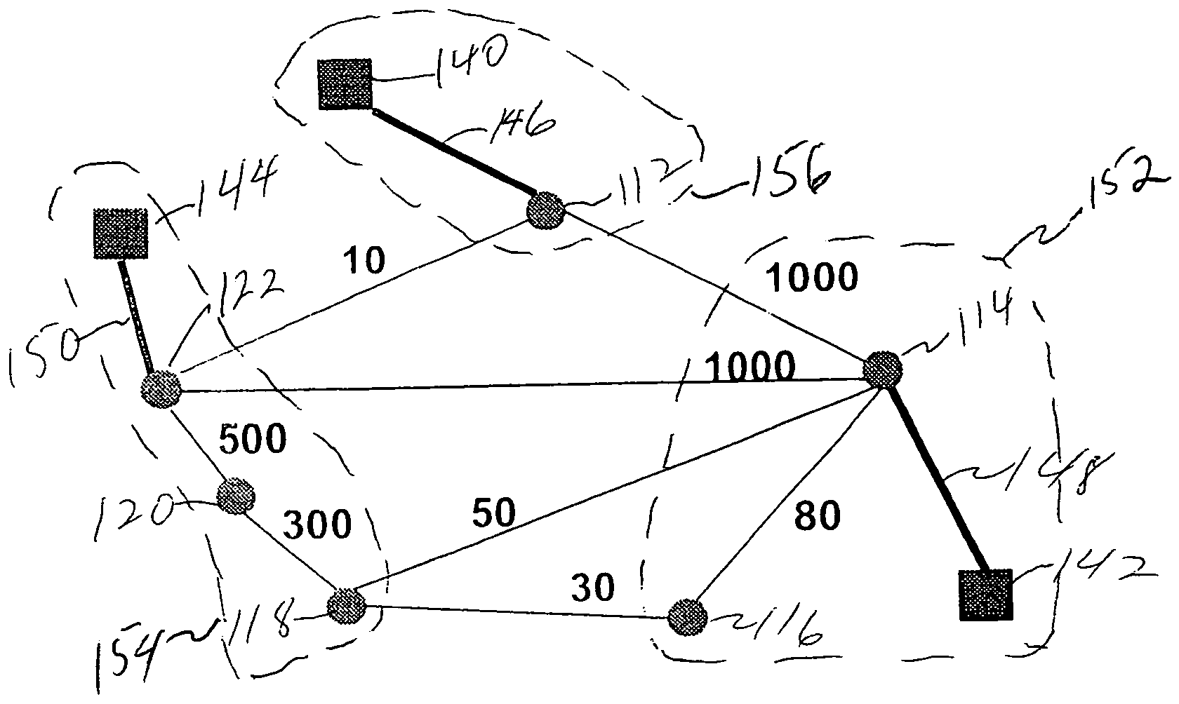
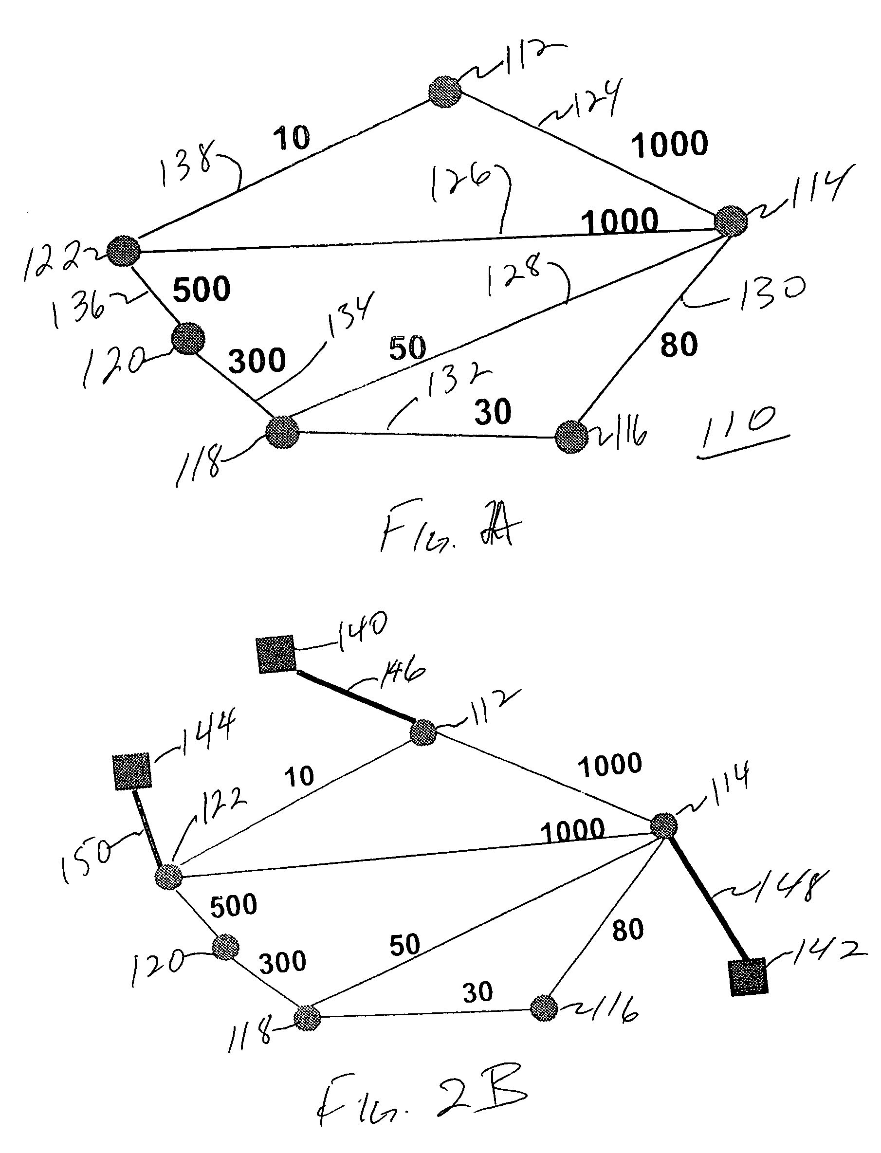
[0025]As referred to herein, a communication graph is a graphical representation of a multifaceted task such as a computer program. Each facet of the task is an independent task or object that is represented as a node and communication between tasks or nodes is represented by a line (referred to as an edge) between respective communicating nodes. Participating individuals (individuals receiving and executing distributed tasks) are referred to as terminal nodes or machine nodes. A net is a collection of nodes connected together by edges. Two nets are independent if none of the non-terminal nodes of one net shares an edge with a non-terminal node of the other. Thus, for example, a communication graph of a computer program might include a node for each program object and edges would be between communicating objects, with edges not being included between objects not communicating with each other. In addition, a weight indicative of the level of communication between the nodes may be ass...


PUM


Abstract

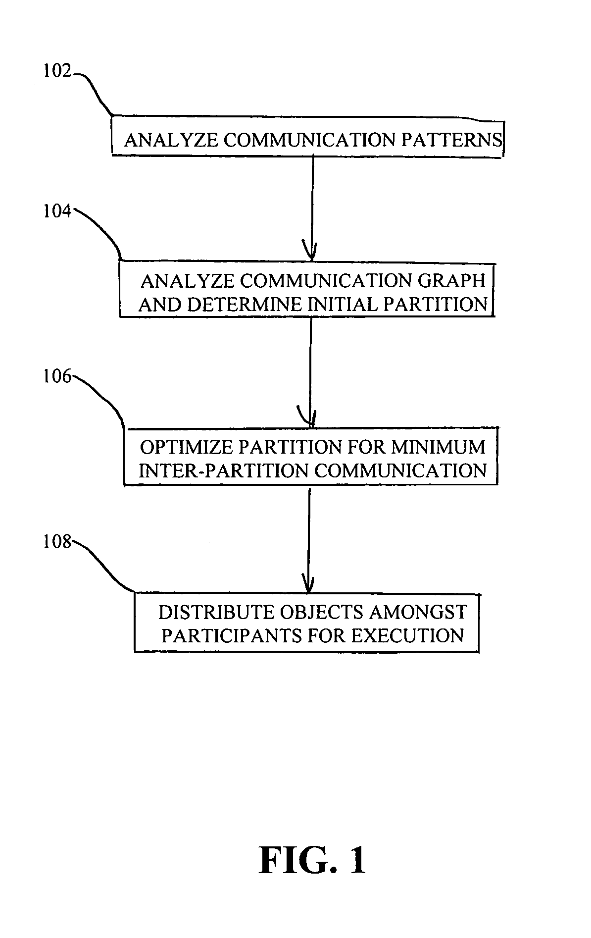
A task management system, method and computer program product for determining optimal placement of task components on multiple machines for task execution, particularly for placing program components on multiple computers for distributed processing. First, a communication graph is generated representative of the computer program with each program unit (e.g., an object) represented as a node in the graph. Nodes are connected to other nodes by edges representative of communication between connected nodes. A weight is applied to each edge, the weight being a measure of the level of communication between the connected edges. Terminal nodes representative of the multiple computers are attached to the communication graph. Then, the communication graph is divided into independent nets and a min cut is found for each independent net. The min cut for the communication graph is the combination of the min cuts for all of the independent nets. Finally, program components which may be a single program unit or an aggregate of units are placed on computers according to the communication min cut.

Description

RELATED APPLICATION[0001]The present application is related to U.S. patent application No. 09 / 676,423 entitled “MACHINE CUT TASK IDENTIFICATION FOR EFFICIENT PARTITION AND DISTRIBUTION” to Rajan et al., now issued as U.S. Pat. No. 6,823,510; U.S. patent application Ser. No. 09 / 676,425 entitled “NET ZEROING FOR EFFICIENT PARTITION AND DISTRIBUTION” to Roth et al., now issued as U.S. Pat. No. 6,862,731; and U.S. patent application No. 09 / 676,424 entitled “DOMINANT EDGE IDENTIFICATION FOR EFFICIENT PARTITION AND DISTRIBUTION” to Wegman et al., now issued as U.S. Pat. No. 6,817,016 all filed coincident herewith and assigned to the assignee of the present invention.BACKGROUND OF THE INVENTION[0002]1. Field of the Invention[0003]The present invention generally relates to distributed processing and more particularly, the present invention relates to efficiently assigning tasks across multiple computers for distributed processing.[0004]2. Background Description[0005]Any large, multifaceted ...

Claims


Application Information

Patent Timeline
IPC IPC(8): G06F9/46
CPCG06F9/5066
Inventor KIMELMAN, DOUGLAS N.RAJAN, VADAKKEDATHU T.ROTH, TOVAWEGMAN, MARK N.HOGSTEDT, KARIN
Owner IBM CORP
Learn More