Apparatus for detecting an end portion of a recording medium

a technology for recording media and antenna, which is applied in the direction of printing, instruments, manufacturing tools, etc., can solve the problems of complex structure of the printer, inability to effectively use the rear end of continuous paper, waste of continuous paper by the unprinted and discarded amount, etc., and achieve the effect of effectively utilizing continuous paper, without complicating the structur

Inactive Publication Date: 2006-03-14
TOSHIBA TEC KK
View PDF16 Cites 16 Cited by
  • Summary
  • Abstract
  • Description
  • Claims
  • Application Information

AI Technical Summary

Benefits of technology

[0012]Accordingly, an object of the present invention is, in a printer having a hopper without shaft, to detect a rear end of continuous paper without upsizing the apparatus and without complicating the structure, and to effectively utilize the continuous paper without causing shortage of the continuous paper during execution of print operation.

Problems solved by technology

Further, in a case where the latter apparatus for detecting an end portion of a recording medium is used, as only the near end of the continuous paper is detected, the continuous paper cannot be effectively used to the rear end, thus the continuous paper is wasted by the unprinted and discarded amount.
Since the encoder is attached to the support shaft and a mechanism to detect the rotation of the encoder is provided, the structure of the printer is complicated.
However, as in the case of the above-described art, since the encoder is attached to the roller and a mechanism to detect the rotation of the encoder is provided, the structure of the printer is complicated.

Method used


Image

  • Apparatus for detecting an end portion of a recording medium
  • Apparatus for detecting an end portion of a recording medium
  • Apparatus for detecting an end portion of a recording medium

Examples


Embodiment Construction

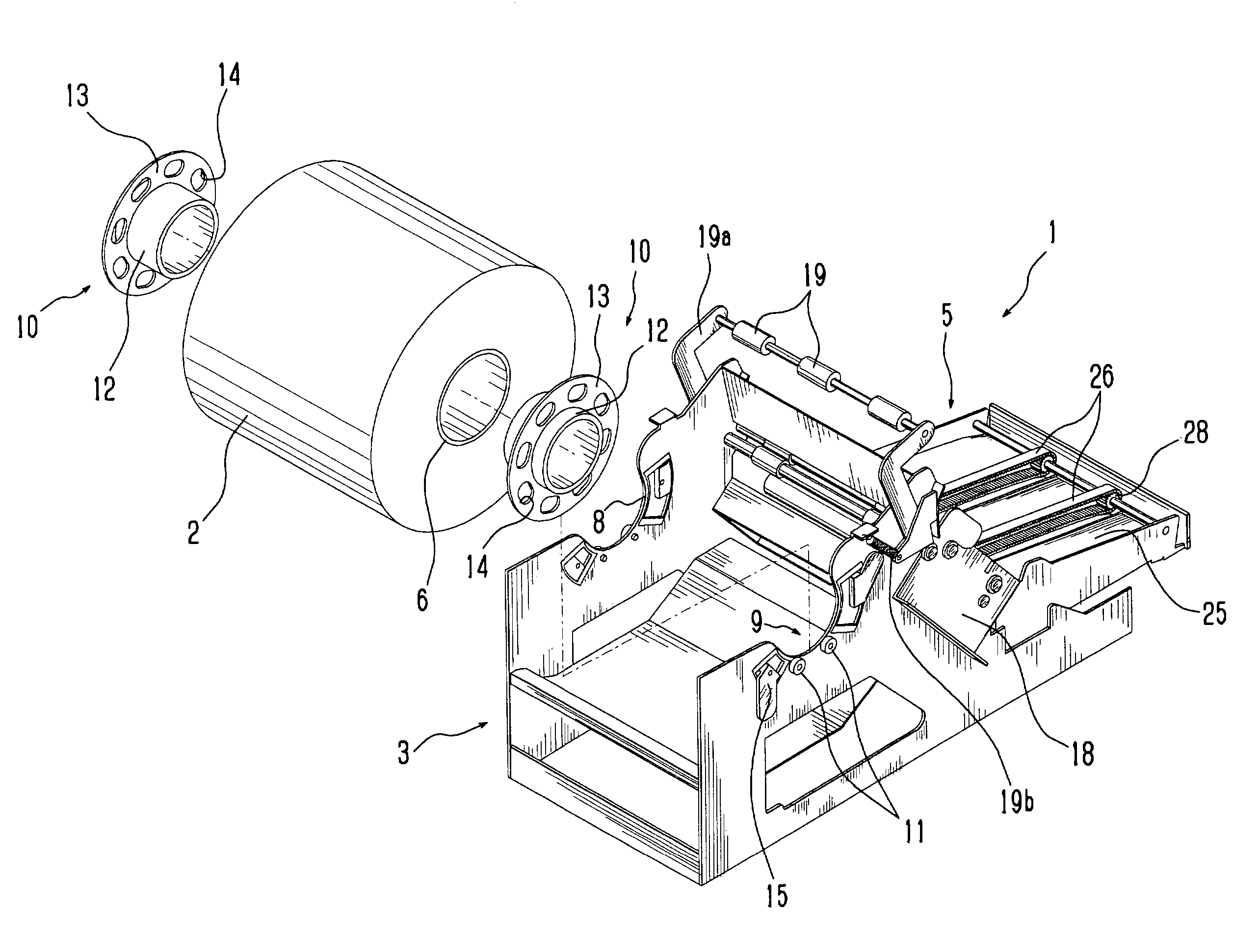
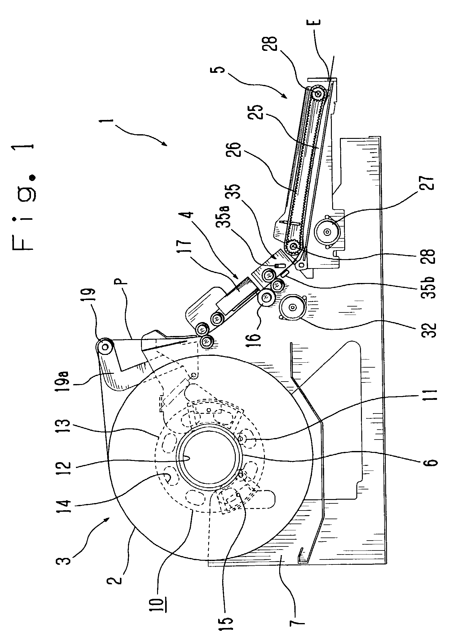
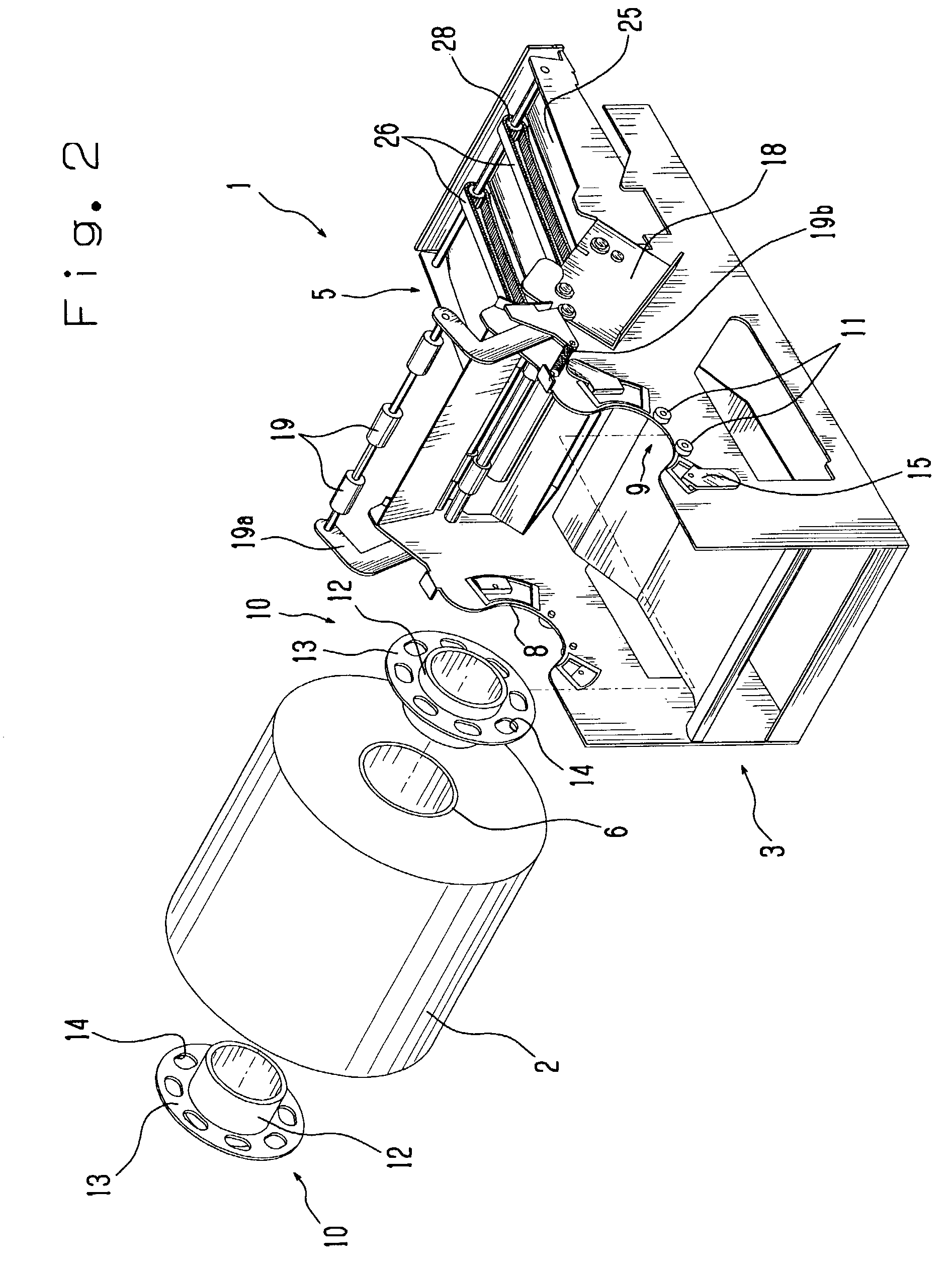
[0028]An embodiment of the present invention will be described in accordance with FIGS. 1 to 7. In the present embodiment, an application to a printer which performs a print operation with a predetermined maximum print size on a roll of continuous paper is shown.

[0029]FIG. 1 is a cross-sectional side view of a printer applied an apparatus for detecting an end portion of a recording medium of the present invention; and FIG. 2, a rear perspective view showing a status where the printer applied an apparatus for detecting an end portion of a recording medium of the present invention is partially exploded. A printer 1 has a hopper 3 accommodating a roll of continuous paper 2, a print unit 4 which performs printing on the continuous paper 2, and a transport unit 5 which conveys the continuous paper 2.

[0030]The hopper 3, the print unit 4 and the transport 5 are communicated with each other via a guide passage P. The guide passage P connecting the hopper 3 to an emitting port E via the prin...


PUM


Abstract

A printer having a hopper without shaft which performs a print operation on a roll of continuous paper. Detection marks are provided in flanges provided in supported members removably attached to the continuous paper, and the presence/absence of the detection mark in a detection position of an optical sensor is determined. A rear end of the continuous paper in the hopper is determined if the result of determination of the presence/absence of the detection mark during conveyance of the continuous paper is the same. A passage length from the position of the determined rear end of the continuous paper to a print unit is equal to or longer than a predetermined maximum print size. By this arrangement, the rear end of the continuous paper can be detected without upsizing the apparatus and without complicating the structure, and the continuous paper can be effectively utilized without causing shortage of the continuous paper during execution of print operation.

Description

BACKGROUND OF THE INVENTION[0001]1. Field of the Invention[0002]The present invention relates to an apparatus for detecting an end portion of a recording medium for applying to a printer which prints a predetermined subject on a roll of continuous paper, and more particularly, to an apparatus for detecting an end portion of a recording medium for applying to a printer which performs a print operation with a predetermined maximum print size.[0003]2. Description of Related Art[0004]Printers which print a predetermined subject on a roll of continuous paper then cut the continuous paper in a position corresponding to a print size are known.[0005]The above printers include a printer having a hopper to accommodate the continuous paper. As the form of accommodation of continuous paper in the hopper, the printers are briefly classified into printer having a hopper with a support shaft to support the center of the continuous paper and a printer having a hopper without such support shaft.[000...

Claims


Application Information

Patent Timeline
Patent Type & Authority Patents(United States)
IPC IPC(8): B41J2/36B41J11/42B26D5/34B41J11/00B41J15/04B65H16/06B65H26/08B65H43/02
CPCB41J15/04B41J11/0075
Inventor SEKINO, TOSHIHARU
Owner TOSHIBA TEC KK
Why Eureka
Try Eureka