
Thrust vectoring a flight vehicle during homing using a multi-pulse motor

a multi-pulse, thrust vectoring technology, applied in the direction of aircraft navigation control, vessel construction, marine propulsion, etc., can solve the problems of adversely affecting other performance characteristics, elusive goals, adversely affecting maneuverability,

Inactive Publication Date: 2006-03-14
LOCKHEED MARTIN CORP
View PDF10 Cites 12 Cited by
  • Summary
  • Abstract
  • Description
  • Claims
  • Application Information

AI Technical Summary

Benefits of technology

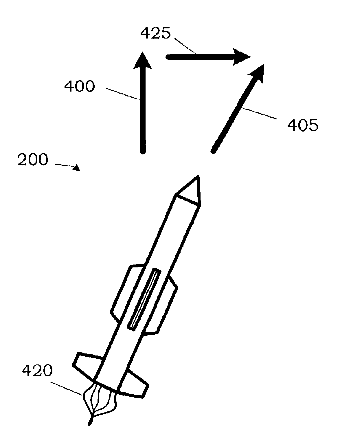
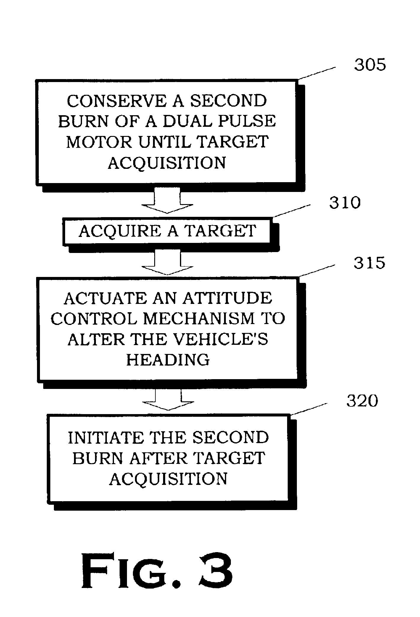
[0012]The present invention, in its various aspects and embodiments, includes method and apparatus for thrust vectoring a flight vehicle during homing. The flight vehicle comprises a body; a plurality of attitude control mechanisms on the body; a multi-pulse motor housed at least partially in the body; and a control unit housed in the body. The control unit generates signals controlling an actuation of the attitude control mechanisms and the multi-pulse motor to initiate a follow-on burn of the multi-pulse motor to effect a maneuver directed by the actuation of the attitude control mechanisms. The method comprises conserving a second burn of a dual pulse motor until target acquisition; acquiring a target; actuating a attitude control mechanism for the flight vehicle to alter the flight vehicle's heading; and initiating the second burn.

Problems solved by technology

Optimal performance, however, can be an elusive goal.
The primary reason for this reality is that the technical solutions for any one characteristic may adversely impact other performance characteristics.
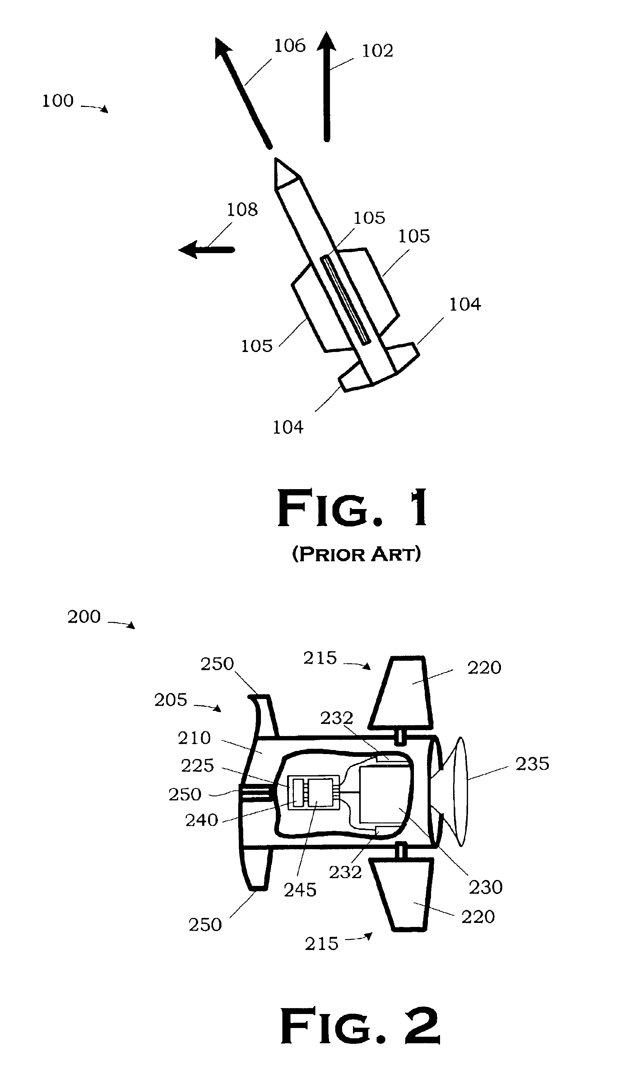
Small fins, however, adversely impact maneuverability because they do not provide as much lift as larger fins. FIG. 1 illustrates a conventional approach to turning a missile 100.
They nevertheless increase weight and drag, thereby reducing speed.
This conundrum becomes more troublesome at high altitudes where thin atmospheres hamper the ability to generate lift adequate to quickly alter the flight path of the missile 100.
Conventional uses of dual pulse motors cause other problems, however.
For example, the increased high end speed exacerbates the problem of decreased reaction time.
Divert motors are a separate system that can cause complications, such as difficulty in integrating into the control systems of the missile 100.
The divert motors also add cost and weight to the missile 100, and generally decrease the reliability of the overall missile system.

Method used


Image

  • Thrust vectoring a flight vehicle during homing using a multi-pulse motor
  • Thrust vectoring a flight vehicle during homing using a multi-pulse motor
  • Thrust vectoring a flight vehicle during homing using a multi-pulse motor

Examples


Embodiment Construction

[0021]Illustrative embodiments of the invention are described below. In the interest of clarity, not all features of an actual implementation are described in this specification. It will of course be appreciated that in the development of any such actual embodiment, numerous implementation-specific decisions must be made to achieve the developers' specific goals, such as compliance with system-related and business-related constraints, which will vary from one implementation to another. Moreover, it will be appreciated that such a development effort, even if complex and time-consuming, would be a routine undertaking for those of ordinary skill in the art having the benefit of this disclosure.

[0022]FIG. 2 depicts, in partially sectioned perspective view, a portion of a flight vehicle 200 in one particular embodiment constructed and operated in accordance with the present invention. The flight vehicle 200 comprises a body 205 including a fuselage 210 and a plurality of attitude control...


PUM


Abstract

A method and apparatus for thrust vectoring a flight vehicle during homing are disclosed. The flight vehicle includes a body; a plurality of attitude control mechanisms on the body; a multi-pulse motor housed at least partially in the body; and a control unit housed in the body. The control unit generates signals controlling an actuation of the attitude control mechanisms and the multi-pulse motor to initiate a follow-on burn of the multi-pulse motor to effect a maneuver directed by the actuation of the attitude control mechanisms. The method includes conserving a second burn of a dual pulse motor until target acquisition; acquiring a target; actuating a attitude control mechanism for the flight vehicle to alter the flight vehicle's heading; and initiating the second burn.

Description

[0001]This application claims the benefit of provisional application Ser. No. 60 / 389,944 filed Jun. 19, 2002.BACKGROUND OF THE INVENTION[0002]1. Field of the Invention[0003]The present invention pertains to control of a motorized flight vehicle in a medium and, more particularly, to thrust vectoring a flight vehicle during homing using a dual pulse solid rocket motor.[0004]2. Description of the Related Art[0005]Flight vehicles such as missiles find a wide range of very demanding applications. They are frequently employed in many different scenarios with varying degrees of lethality. These scenarios may range from non-lethal missions to the delivery of an explosive payload to disable, or even destroy, a target. Because of this potential lethality, much consideration is devoted to the design of such flight vehicles to achieve optimal performance. Optimal performance, however, can be an elusive goal. The primary reason for this reality is that the technical solutions for any one charac...

Claims


Application Information

Patent Timeline
Patent Type & Authority Patents(United States)
IPC IPC(8): F41G7/00F02K9/28F02K9/42F02K9/80F02K9/94F42B10/64F42B10/66F42B15/01
CPCF02K9/28F02K9/42F02K9/80F42B15/01F42B10/64F42B10/66F02K9/94
Inventor BROWN, CHARLES C.BEYER, PHILIP T.
Owner LOCKHEED MARTIN CORP
Learn More