
Apparatus for converting ocean wave energy into electric power

Inactive Publication Date: 2006-03-14
KUN SHAN UNIVERSITY
View PDF18 Cites 45 Cited by
  • Summary
  • Abstract
  • Description
  • Claims
  • Application Information

AI Technical Summary

Problems solved by technology

Such multiple energy conversions can consume energy significantly, i.e., lower energy conversion efficiency.
Further, they can complicate the electric generation system, resulting in an increase in the installation and maintenance costs.
This is not desirable.

Method used


Image

  • Apparatus for converting ocean wave energy into electric power
  • Apparatus for converting ocean wave energy into electric power
  • Apparatus for converting ocean wave energy into electric power

Examples


Embodiment Construction

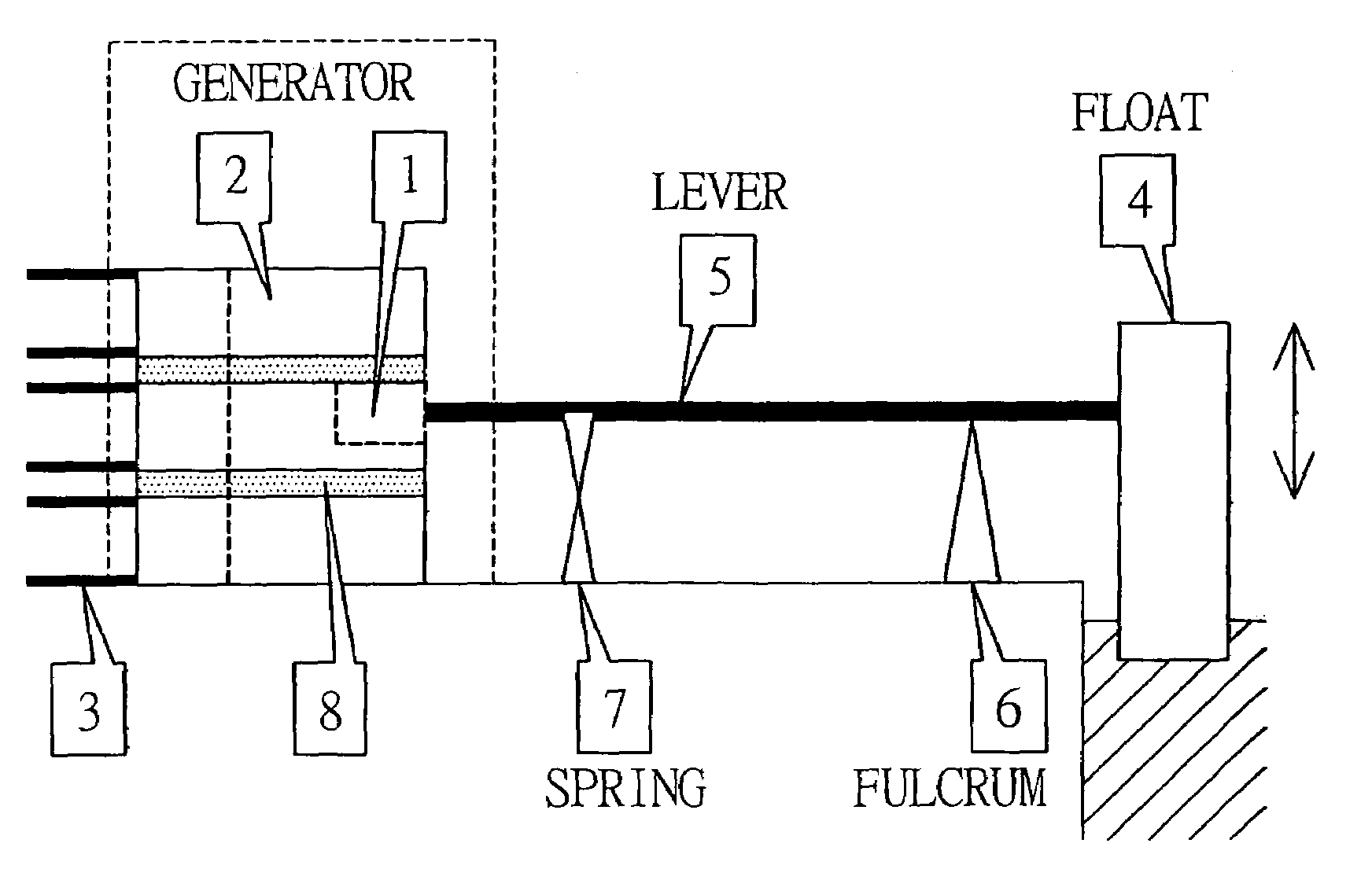
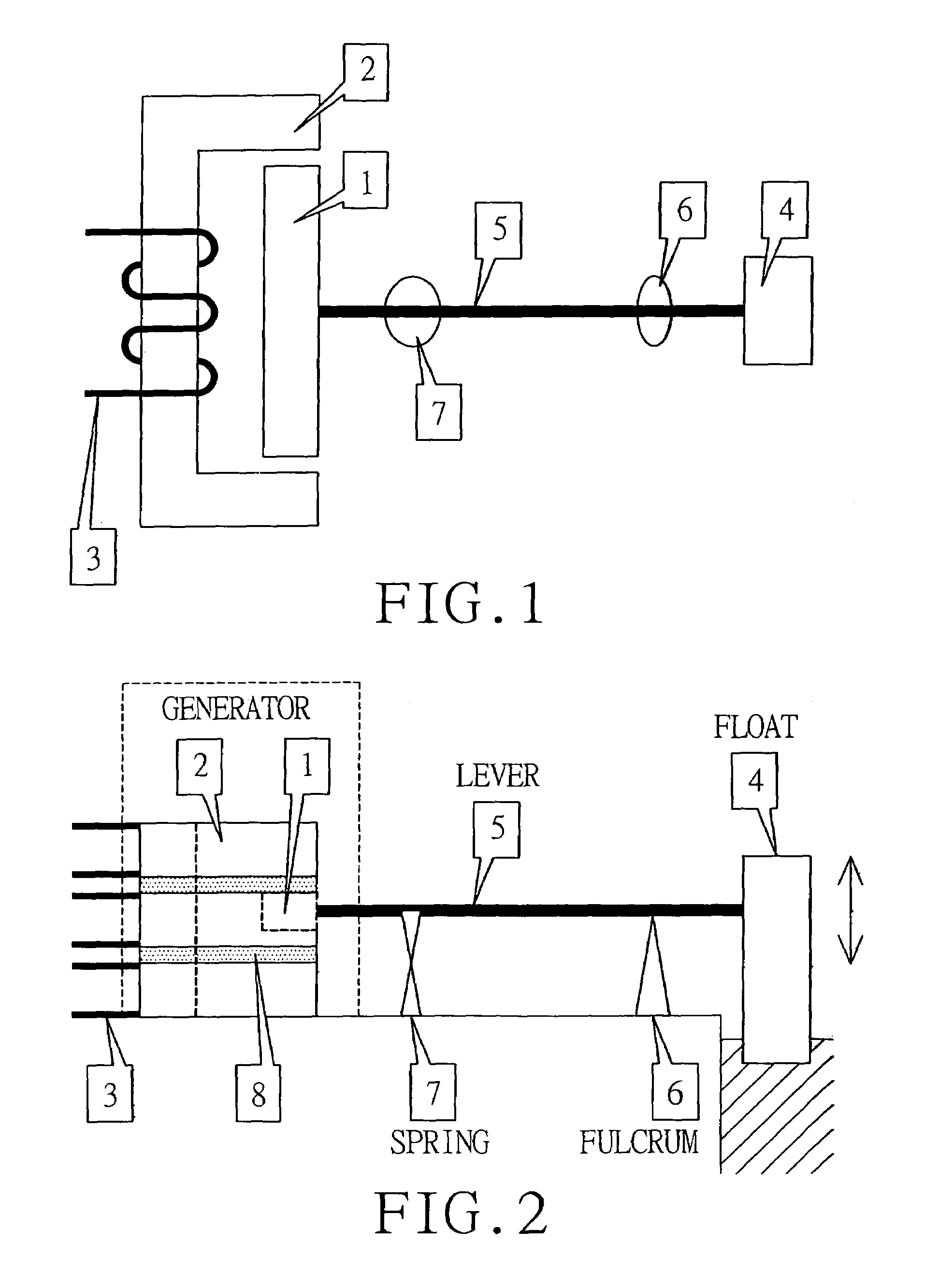
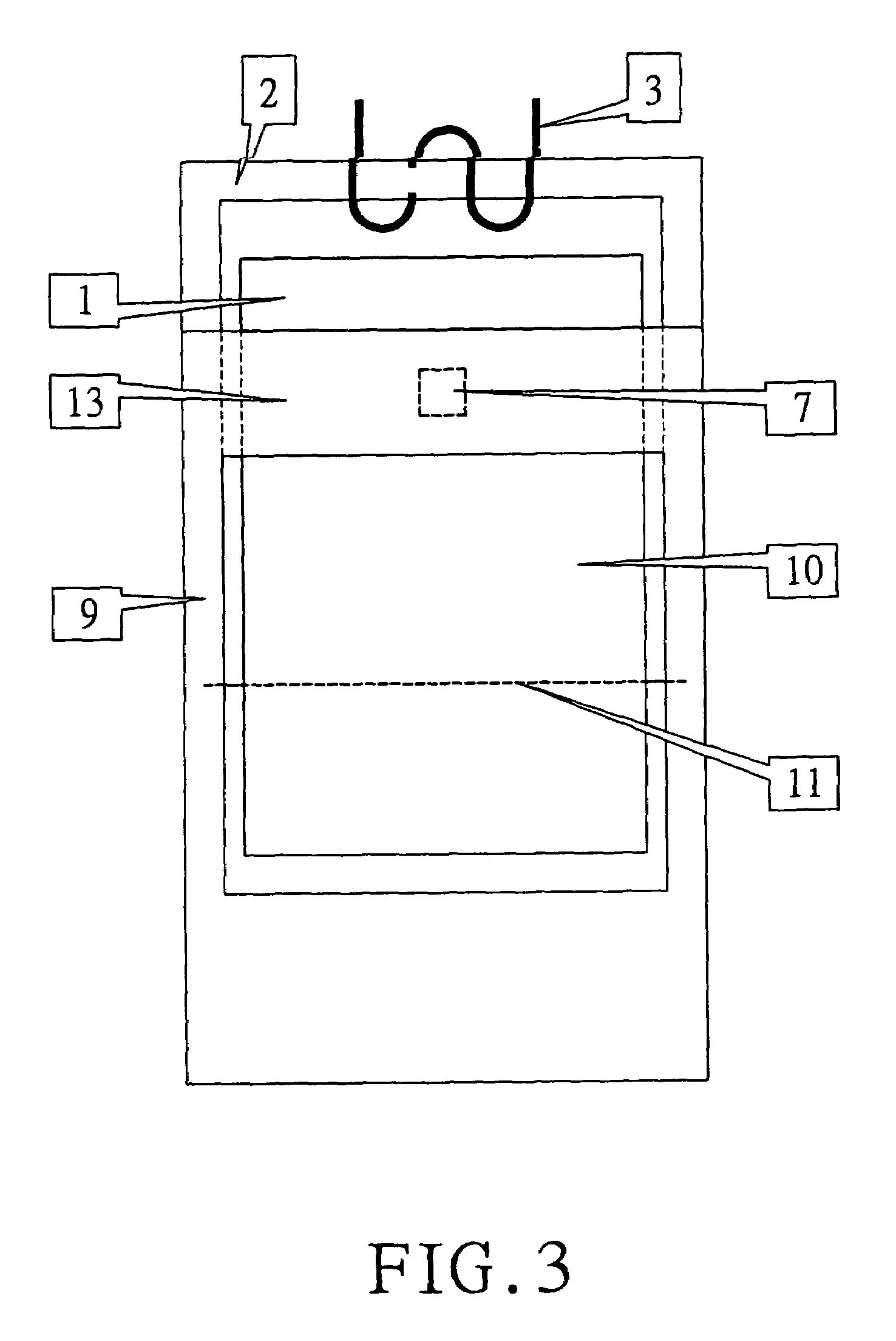
[0015]Referring to FIGS. 1 and 2, there is shown an apparatus constructed in accordance with a first preferred embodiment of the invention. The apparatus comprises a float 4 adapted to ride on the surface of the ocean in reciprocal vertical motion in response to ocean wave front action, and a lever 5 also adapted to ride on the surface of the ocean. The lever 5 has one end coupled to the float 4. On a seacoast, ship, or production platform, the apparatus further comprises a fulcrum 6 pivotally supporting the lever 5. A magnet 1 is coupled to the other end of the lever 5. A plurality of (three shown) parallel stator cores 2 together with the magnet 1 form a magnetic circuit. A plurality of (three shown) parallel electric coils 3 are wound on the stator cores 2. A spring 7 is located adjacent the magnet 1 and interconnected to the lever 5 and the magnet 1. Each of a plurality of barriers 8 is disposed between adjacent stator cores 2.

[0016]The characteristics of the first preferred emb...


PUM


Abstract

An ocean wave energy conversion apparatus includes a float adapted to ride on the surface of the ocean in reciprocal vertical motion in response to ocean wave front action and a lever adapted to ride on the surface of the ocean. The lever has one end coupled to the float. A fulcrum pivotally supports the lever. A magnet is coupled to the other end of the lever. Parallel stator cores having electric coils wound thereon together with the magnet form a magnetic circuit. Springs are adjacent the magnet and interconnected to the lever and the magnet. A barrier is disposed between adjacent stator cores. The upward motion of the float caused by impact of waves will move the magnet downward by the lever and compresses the springs. Downward motion of the float will move the magnet upward by the lever and expand the springs. Repeated movement of the magnet will induce a voltage in the electric coils.

Description

BACKGROUND OF THE INVENTION[0001]1. Field of the Invention[0002]The present invention relates to energy conversion and more particularly to an apparatus for converting ocean wave energy into electric power with improved characteristics.[0003]2. Description of Related Art[0004]It is known that waves move up and down or back and forth with a curving motion. Ocean wave power plants have been developed by placing a power generator unit on a float in the sea. Electricity is generated by the generator by absorbing energy of waves as the waves continuously move therethrough. Conventionally, a hydraulic turbine or gas turbine is installed in a wave power generator. A turbine is a rotary device per se. This gives an impression that electricity can be generated only by a turbine or the like. The prior turbine based electricity generation suffered from several disadvantages. For example, energy of waves is converted into high pressure liquid or air which in turn impinges the vanes of a hydraul...

Claims


Application Information

Patent Timeline
IPC IPC(8): F03B13/12B63H1/38E02B9/08H02K33/00F03B13/18
CPCF03B13/1815Y02E10/38Y02E10/30
Inventor YI, JWO-HWU
Owner KUN SHAN UNIVERSITY
Learn More