
Electric power generator equipment

a technology of electric power generator and equipment, which is applied in the direction of electric generator control, machines/engines, nuclear engineering, etc., can solve the problems of social problems, serious problems, and environmental destruction, and achieve the effect of reducing costs and efficient generating electric power

Inactive Publication Date: 2006-03-14
MATSUBARA TADAHIRO
View PDF3 Cites 24 Cited by
  • Summary
  • Abstract
  • Description
  • Claims
  • Application Information

AI Technical Summary

Benefits of technology

[0009]In order to taking the above-mentioned problems into consideration, it is an object of the present invention to provide an electric power generator equipment capable of efficiently generating electric power and capable of reducing cost, without a water bath and constructive maximum height, in the electric power generator equipment for making a pair of floating bodies alternatively move up and down by buoyant force, in order to carrying out an electric power generation.

Problems solved by technology

As a result, destruction of environment and pollution problem may occur on large-scale and serious problem may occur socially.
However, the location is defined and equipment cost becomes expensive in the electric power generator equipment using natural energy.
As a result, it is difficult to dissolve the problem of cost versus actual performance.
The construction cost is expensive in the water bath and the cost is expensive on saving water in the water bath.
As a result, it is difficult to efficiently generating electric power in the above-mentioned electric power generator equipment.

Method used


Image

  • Electric power generator equipment
  • Electric power generator equipment
  • Electric power generator equipment

Examples


Embodiment Construction

[0052]With reference to the drawings, description will be made as regards an embodiment according to the present invention.

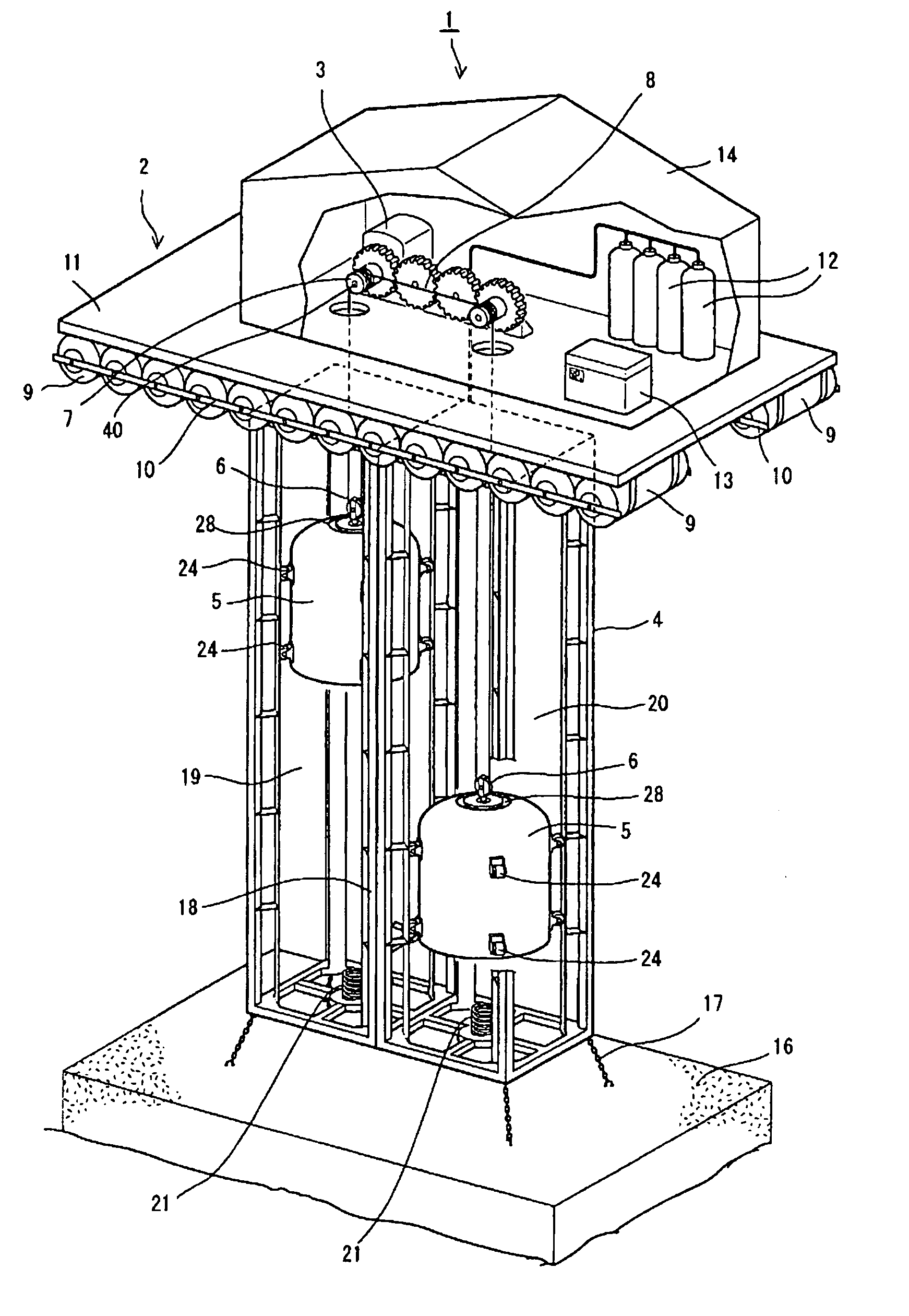
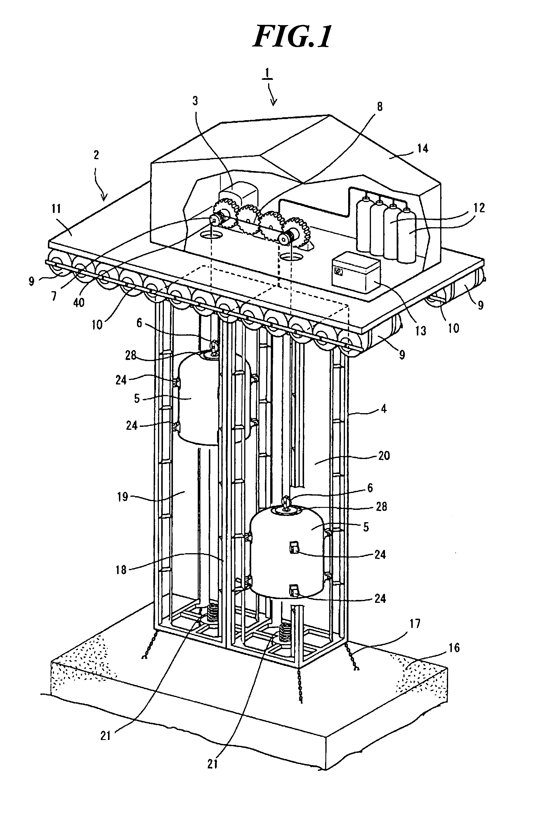
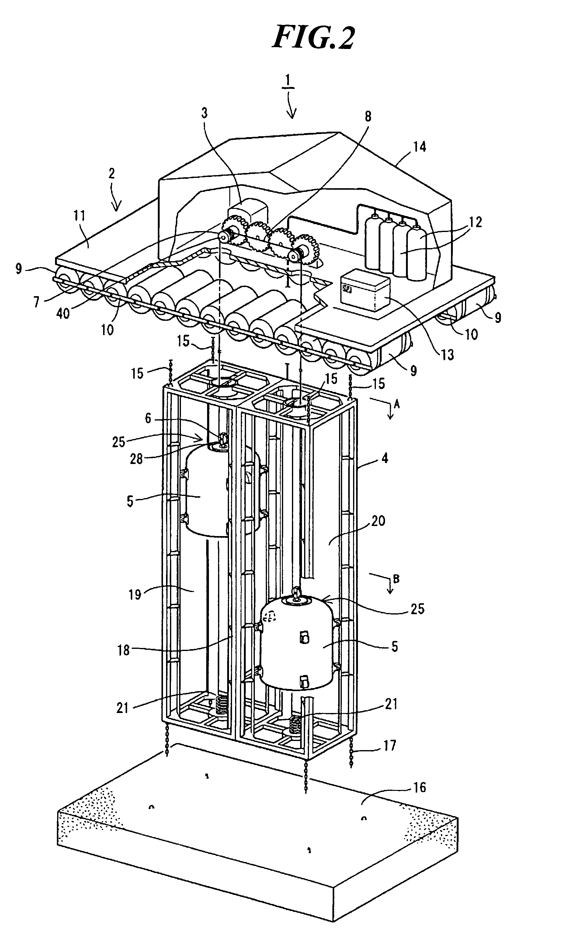
[0053]In FIGS. 1 and 2, reference numeral 1 represents an electric power generator equipment of the present invention. The electric power generator equipment 1 comprises a floating member 2, a power generator 3, cage 4, a pair of hanging bell shaped floating bodies 5, a wire rope 8, and an air filling-up apparatus (not shown). The floating member 2 floats on a water surface of a lake, sea, an impoundment, a reservoir, or the like. The power generator 3 is installed on a upper surface of the floating member 2. The cage 4 is hung on a lower surface of the floating member 2 and is held on a water bottom. The cage 4 is separated into left and right sections and the floating bodies 5 are installed in the left and the right sections, respectively. The both ends of the wire rope 8 is fixed on the cage 4 and is winded to pulleys which are installed on an upper ends of t...


PUM


Abstract

In order to obtain an electric power generator equipment capable of efficiently generating electric power and capable of reducing cost, without a water bath and constructive maximum height, the electric power generator equipment comprises a floating member for floating on a water surface, a power generator installed on an upper surface of the floating member, a cage suspended from a lower end of the floating member and held to a water bottom, a pair of floating bodies positioned in the cage which is separated, a wire rope whose both ends are fixed to the cage, and an air filling-up apparatus for filling up air to each of the floating bodies. The wire rope is winded to a pulley installed an end portion of each floating body and is winded to a pulley installed on the power generator.

Description

CROSS-REFERENCE TO RELATED APPLICATIONS AND CLAIM TO PRIORITY[0001]This application claims priority according to 35 U.S.C. § 119 to patent application number 2004-212403, filed Jul. 21, 2004 in Japan, the disclosure of which is incorporated herein by reference.FIELD OF THE INVENTION[0002]The present invention relates to electric power generator equipment, and more particularly, to electric power generator equipment having a pair of floating bodies which are positioned in water. The electric power generator equipment alternatively fills up and exhausts air of the floating bodies and makes the floating bodies alternatively move up and down by buoyant force, in order to carrying out an electric power generation.BACKGROUND OF THE INVENTION[0003]In general, each of hydraulic power equipment, thermal power equipment, and atomic power equipment are widely known as electric power generator equipment. Each of the hydraulic power equipment, the thermal power equipment, and the atomic power eq...

Claims


Application Information

Patent Timeline
Patent Type & Authority Patents(United States)
IPC IPC(8): F03B13/10F03B17/02
CPCF03B17/025Y02E10/20
Inventor MATSUBARA, HIDEO
Owner MATSUBARA TADAHIRO
Learn More