Clogged filter detector

a filter detector and filter technology, applied in the field of air filters, can solve the problems of clogging and requiring additional energy consumption, ineffective devices of this type for low-speed residential and commercial hvac systems, and energy loss and was

Inactive Publication Date: 2006-03-14
WILSON DAVID J
View PDF10 Cites 78 Cited by
  • Summary
  • Abstract
  • Description
  • Claims
  • Application Information

AI Technical Summary

Benefits of technology

[0014]Component support structure for systems of the invention may comprise a bracket in the form of a thin but rigid base member conforming to a plate of a filter receptacle against which a side face of a border strip of the peripheral framework of the filter is removably positioned, the receptacle also having a restraining ledge integral with and at a right angle to the plate, the ledge securing filter framework from moving in the direction of air flow. The bracket has a first side portion connectible to the ledge with a clip or the lik...

Problems solved by technology

Filters for heating, ventilation and air conditioning systems (HVAC) play an important role by preventing cooling coils and heating surfaces from becoming coated with dust particles, which would result in a loss of efficiency and waste of energy.
After a period of operation, dust accumulates on the filters, causing them to become clogged and requiring additional energy consumption.
HVAC equipment manufacturers typically state their warranties so that the user, not the manufacturer, is responsible for equipment failures due to neglect in maintaining the system, with emphases on the system dust filter.
Various clogged air filter detection devices based on differential pressure monitoring have been developed in prior art for use in higher air veloc...

Method used


Image

  • Clogged filter detector
  • Clogged filter detector
  • Clogged filter detector

Examples


Embodiment Construction

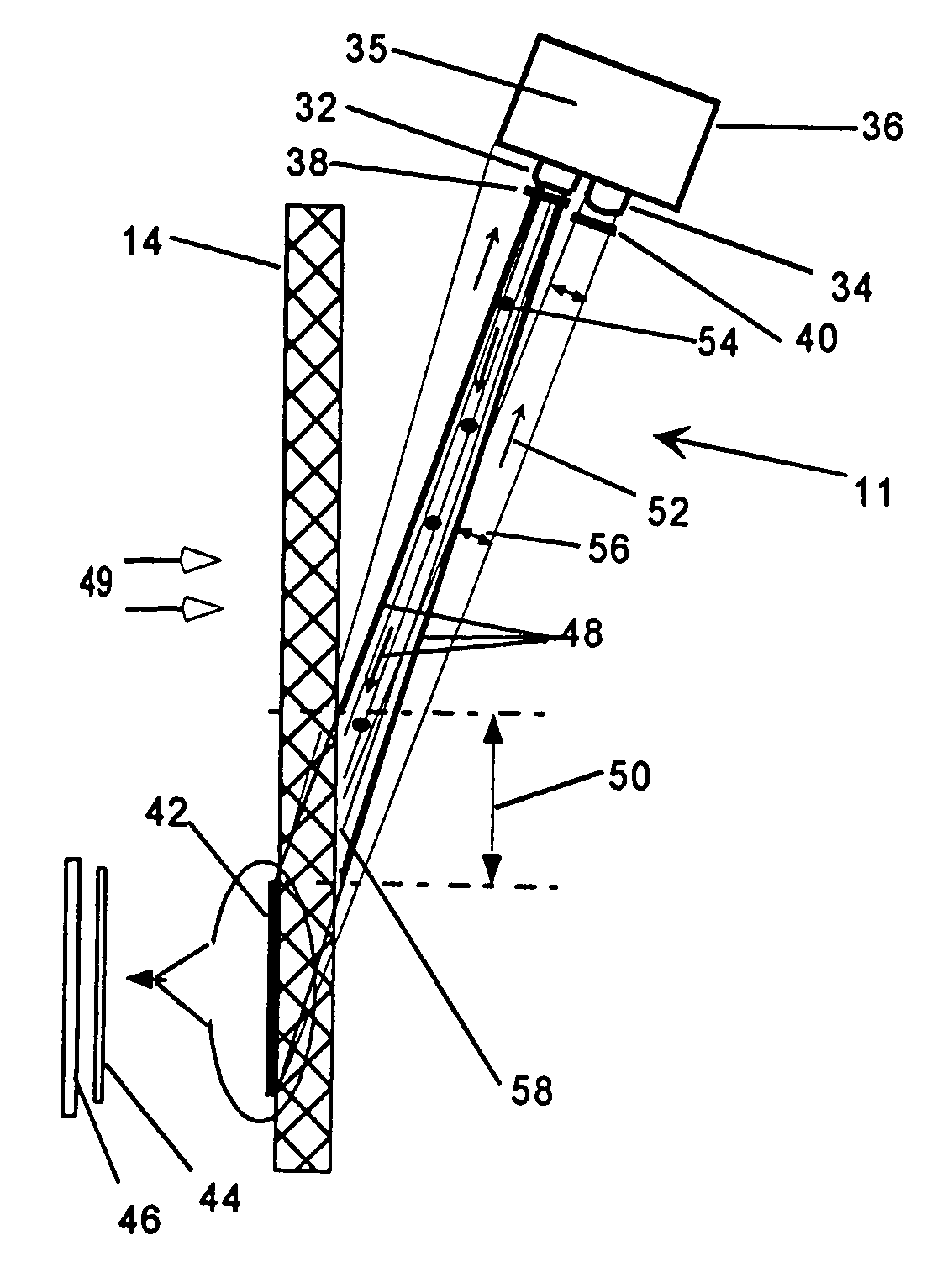
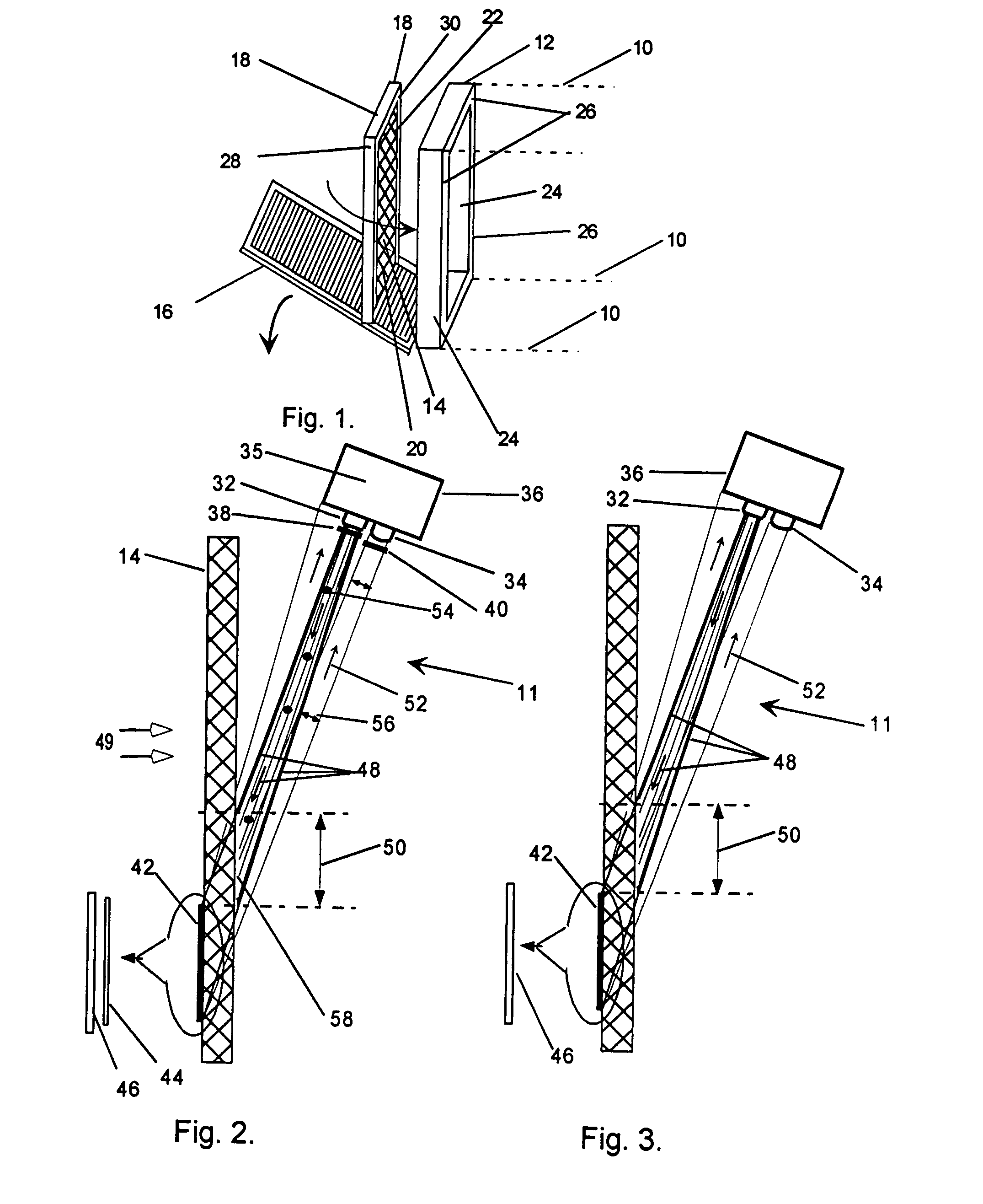
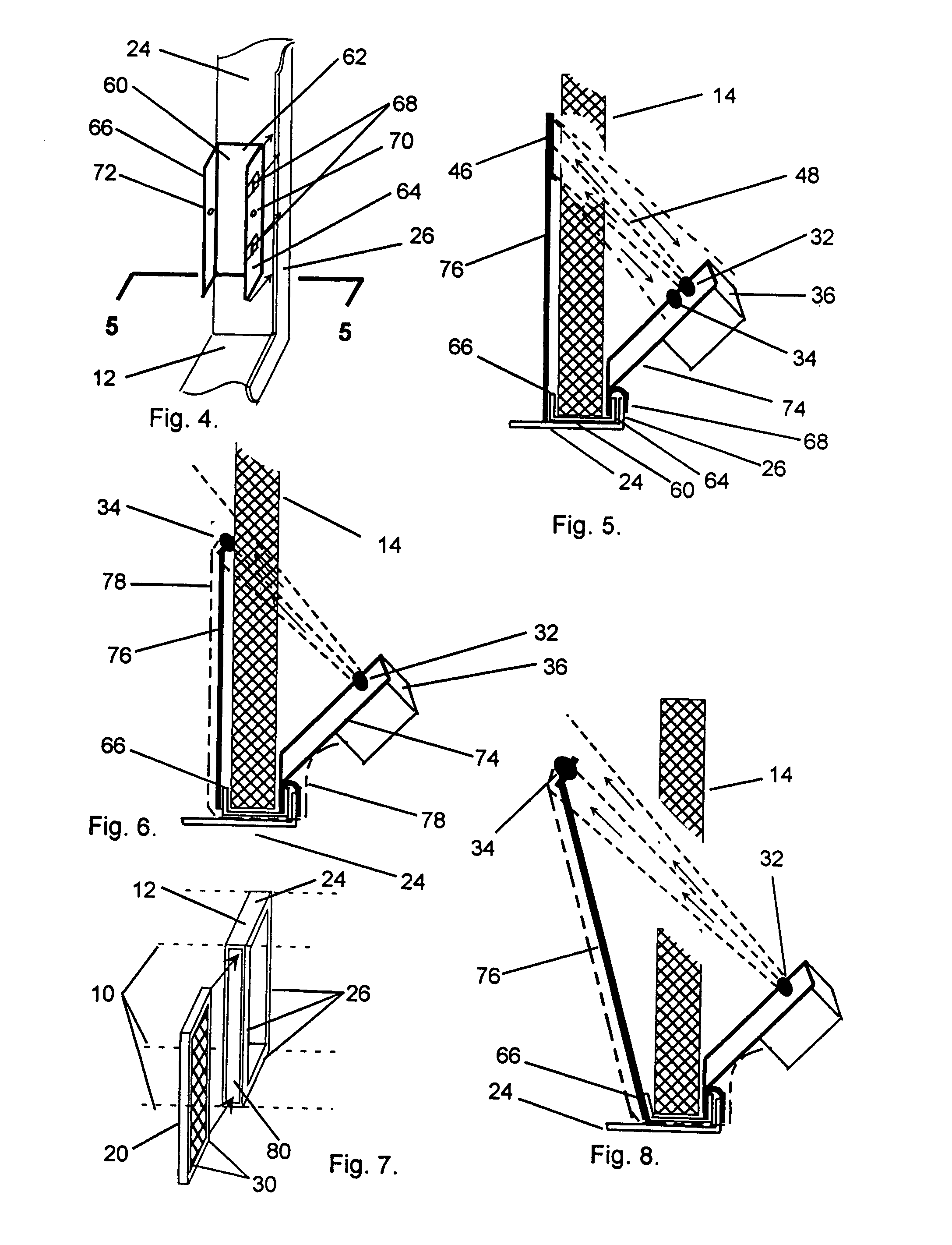
[0037]Referring to FIG. 1 of the drawings there is shown a terminal portion of a HVAC plenum 10 (in dotted lines) in which a filter receptacle 12 and a grill 16, connected to the receptacle by means not shown, are aligned for being placed over a filter 14. The filter has an external frame 18 supporting the filter body 20 which is made up of fiber glass or the like and is either self supporting or held in place by mesh 22 on both sides. Receptacle 12 has four side plates 24 with inner surfaces parallel to the direction of airflow and ledges 26 integral with and disposed perpendicular to the plates. Upon insertion of the filter into the receptacle, side edges 28 of the filter fit against inner surfaces of plates 24 and downstream side border faces 30 come into contact with ledges 26, which restrain the filter from moving downstream.

[0038]FIG. 2 schematically depicts a clogged air filter detection system 11 positioned to monitor the obscuration level in filter 14 and to provide an indi...


PUM

PropertyMeasurementUnit
Angleaaaaaaaaaa
Angleaaaaaaaaaa
Areaaaaaaaaaaa

Abstract

A clogged filter detection system has an optical transmitter (32) aligned to pass light through an air filter (14) of an HVAC air flow plenum, a receiver (34) including a sensor and positioned to receive the transmitted light (48) directly or from a reflector (42), a processing assembly (35) receiving signals from the sensor and communicating a visual (104) or audible (106) indication when an accumulated level of obscuration exceeds a predetermined level and a component support structure. The support structure uses a “U” or “L” shaped bracket (60,63) attached to peripheral structure of a filter receptacle frame (12) and one or more side plates (24,26) of the bracket are connected to an arm (74,76) on which components are carried. The transmitter (32) and receiver (34) may be located on opposite sides of the filter (14) or on the same side, with a retroreflector (46) on the other side. The processing assembly includes a microprocessor (94) and related devices. Measures are also provided for counteracting the presence of fluffy material near the filter, for sensitivity control of sensors and for an aural signal device activated at a predetermined time after a visual indication.

Description

CROSS REFERENCE TO RELATED APPLICATIONS[0001]This application is a continuation-in-part of Application PCT / US02 / 24760, filed 1 Aug. 2002, which in turn claims the benefit of Provisional Application Ser. No. 60 / 310,377, filed Aug. 6, 2001, now abandoned, by the present applicant.FIELD OF THE INVENTION[0002]This invention relates to air filters and more particularly to devices for determining when air filters have become clogged.BACKGROUND OF THE INVENTION[0003]Filters for heating, ventilation and air conditioning systems (HVAC) play an important role by preventing cooling coils and heating surfaces from becoming coated with dust particles, which would result in a loss of efficiency and waste of energy. After a period of operation, dust accumulates on the filters, causing them to become clogged and requiring additional energy consumption. At some point it becomes cost-effective to remove the filter and either clean it or replace it with a new one. HVAC equipment manufacturers typicall...

Claims


Application Information

Patent Timeline
IPC IPC(8): G01N21/00F24F8/10
CPCB01D46/0086B01D46/10F24F11/001F24F3/1603B01D2273/26F24F2011/0093F24F2011/0049F24F11/30F24F2110/00F24F2130/20F24F11/39F24F8/10F24F11/52F24F11/526
Inventor WILSON, DAVID J.
Owner WILSON DAVID J
Why Eureka
Try Eureka