Toilet and sink drain plunger

a technology for sink drains and plungers, which is applied in the field of toilets and sink drain plungers, can solve the problems of drain pipe connections loosening, requiring considerable force, and the cup is initially difficult to compress by the handle, and achieves the effects of convenient fabrication and use, low cost and durabl

Inactive Publication Date: 2006-03-21
GEORGE TASH & DEBRA B TASH AS TRUSTEES OF THE COMMUNITY TRUST CREATED UNDER THE GEORGE TASH & DEBRA B TASH INTER VIVOS TRUST AGREEMENT DATED NOVEMBER 25 1985 AS AMENDED & TOTALLY RESTATED ON MAY 19 1999
View PDF7 Cites 8 Cited by
  • Summary
  • Abstract
  • Description
  • Claims
  • Application Information

AI Technical Summary

Benefits of technology

[0007]Accordingly, there is a need for an improved type of toilet and sink drain plunger which can seat securely over or in the toilet or sink drain hole, regardless of the curvature of the area around the drain hole. Such plunger should be simple, efficient, capable of being easily fabricated and used and be inexpensive and durable.

Problems solved by technology

The cup is initially very difficult to compress down by the handle, requiring considerable force.
This frequently results in loosening of the drain pipe connections and water leakage therefrom.
The seal between the bottom end of the cup and the area around the sink or toilet drain hole is frequently inadequate and the cup may slip about over the area, reducing the suction afforded by the cup.
Toilets and sinks have various curvatures in the area surrounding the drain hole, making difficult the proper seating of conventional drain plungers, especially toilet drain plungers such as the above-described cup plunger.
But even that plunger is unable to seat securely over and hold in place around curtain toilet drain holes, due to the curved configuration of the toilet around the drain hole.

Method used


Image

  • Toilet and sink drain plunger
  • Toilet and sink drain plunger
  • Toilet and sink drain plunger

Examples


Embodiment Construction
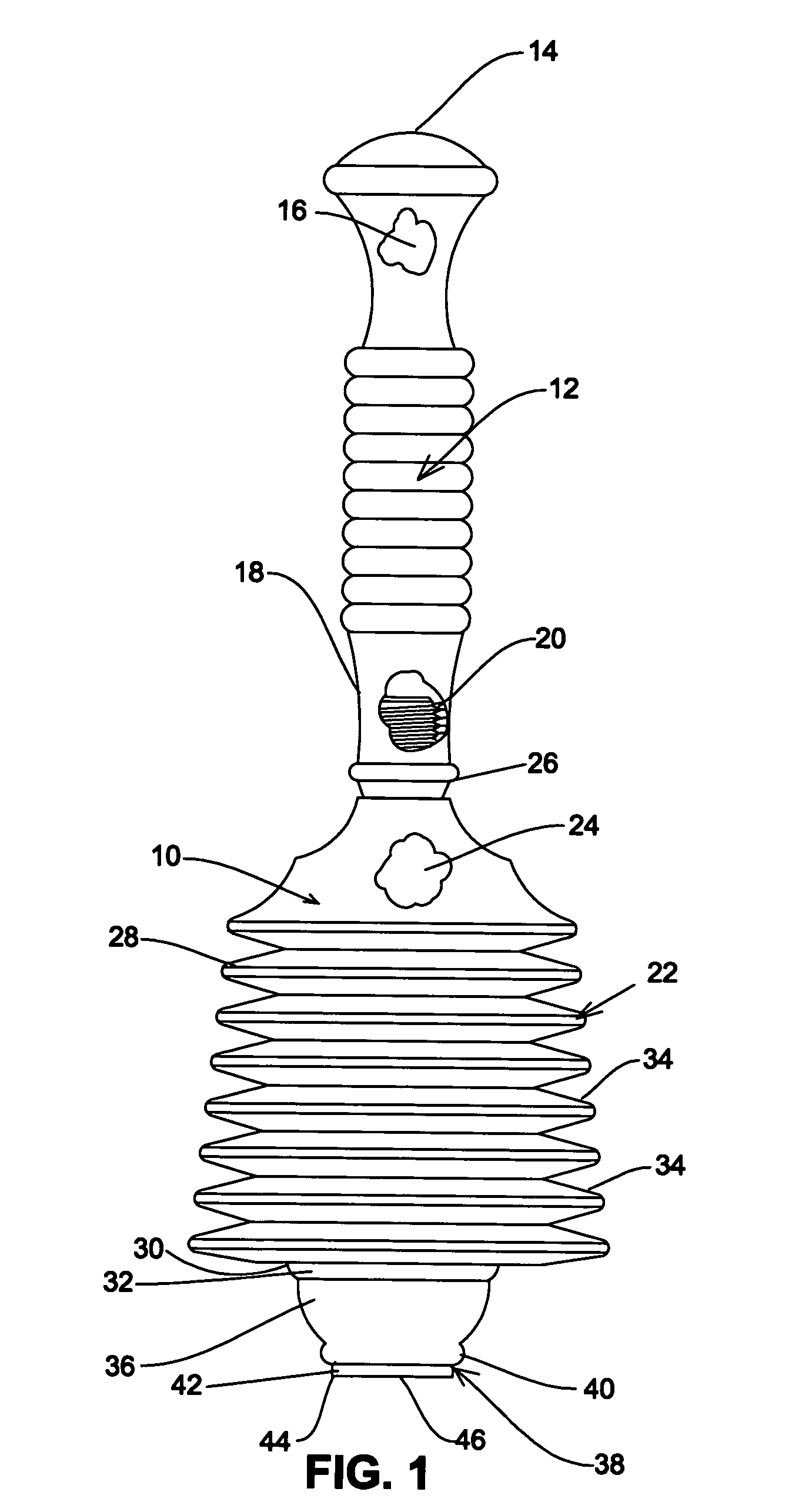
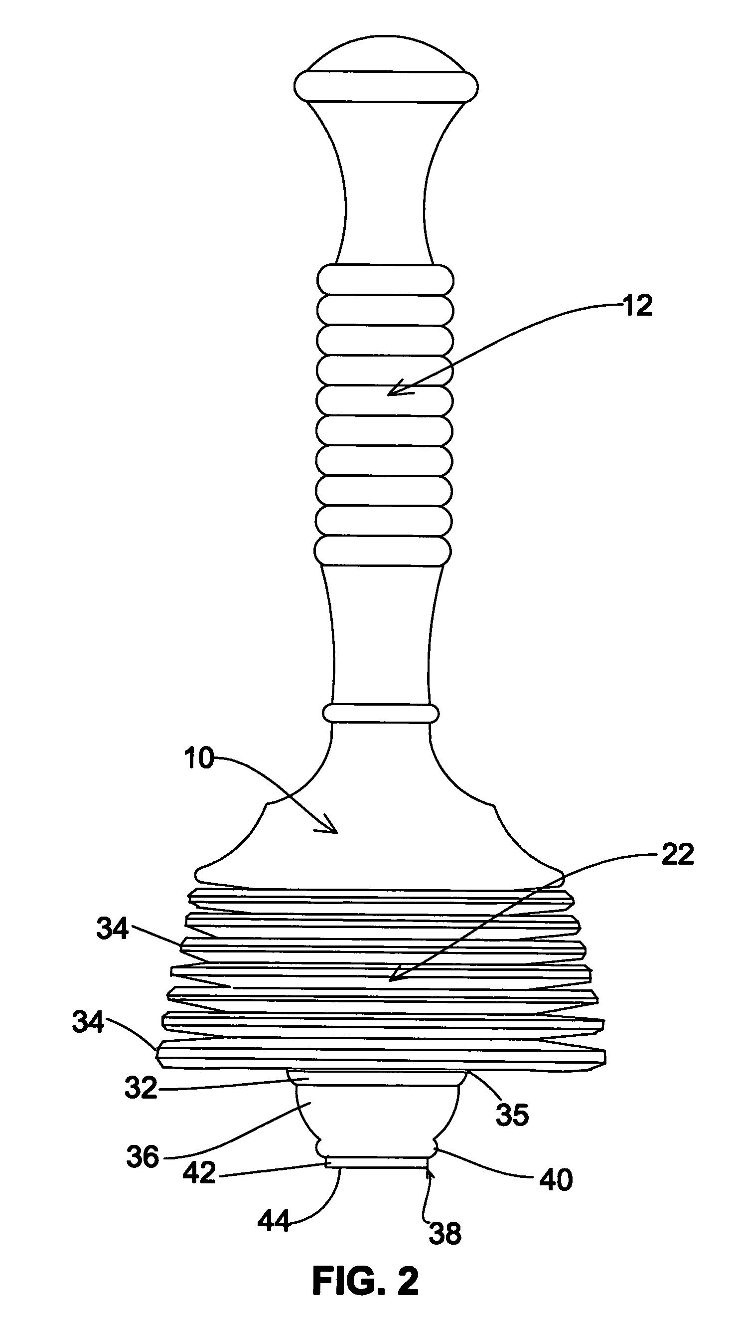
FIGS. 1–3:

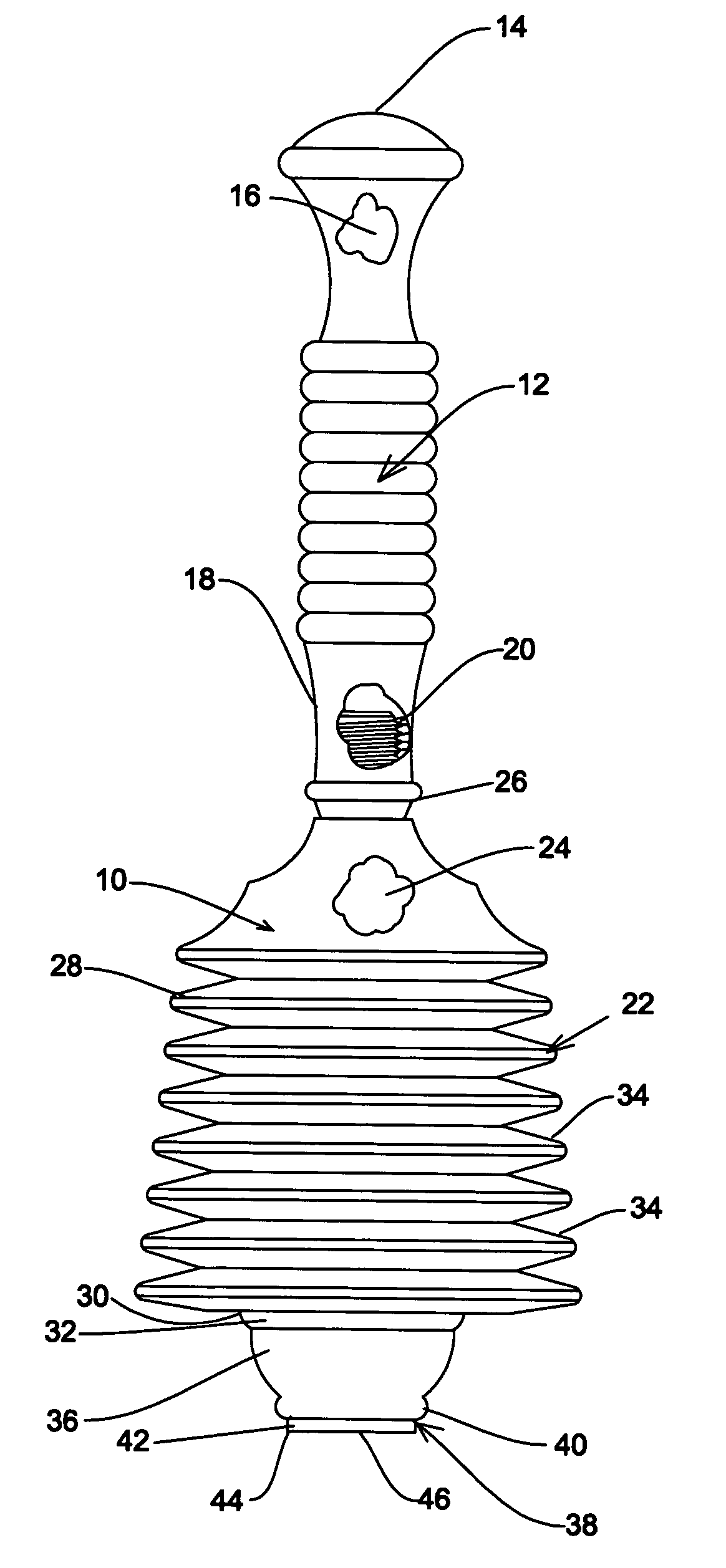
[0016]Now referring more particularly to FIGS. 1–4 of the drawings, a preferred embodiment of the improved toilet and sink drain plunger of the present invention is schematically depicted therein. Thus, plunger 10 is shown, which comprises an elongated vertical handle 12, the upper end of which is formed into an expanded knob 14 adapted to comfortably rest in the palm of the hand of the plunger user. Preferably, handle 12 is hollow, having a central space 16 therein to reduce its weight, and can, if desired, be formed of moldable, rigid, light weight plastic such as high density polyethylene plastic or the like.

[0017]The bottom portion 18 of handle 12 may include external integral threads 20 so that handle 12 can be releasably connected to the bellows 22 of plunger 10. Alternately the entire plunger 10 can be of unitary construction.

[0018]Bellows 22 is generally frusto-conical in shape, has a central space 24 extending therethrough defined by a closed transversely extendin...


PUM


Abstract

The present toilet and sink drain plunger seals either around or in a toilet or sink drain hole despite the hole's size, configuration and location. The plunger includes an elongated upstanding handle connected to the top of a depending, preferably frusto-conical, open bottomed bellows in the sidewalls of which are formed a vertically stacked series of interconnected horizontal pleats. The plunger further includes a series of toilet drain hole seals connected to each other and to the bottom of the bellows to form a unitary whole depending below the bellows. The seals are of progressively smaller size from the uppermost to the lowermost and all feature inwardly and downwardly curved sealing surfaces. The seals are rings or doughnuts molded into the plunger body. The bottommost seal bears a short vertical small diameter annular wall depending therefrom and which acts both as a seal and a seat for the plunger. The entire plunger can be formed in a single plastic molding operation or, if desired, in separate molding operations for the handle and remainer of the plunger. The plunger is efficient, light in weight, inexpensive and durable.

Description

IDENTIFICATION OF RELATED APPLICATION[0001]This application is a continuation-in-part of U.S. patent application Ser. No. 08 / 432,245, filed on Apr. 27, 1995, and entitled “Improved Toilet Drain Plunger”, now abandoned.BACKGROUND OF THE INVENTION[0002]1. Field of the Invention[0003]The present invention generally relates to water and sewage drain decloggers and more particularly to an improved type of toilet and sink drain plunger.[0004]2. Prior Art[0005]The usual type of plunger used for declogging sinks and toilet drains and the like comprises a vertical wooden or metal handle, to the bottom of which is secured an inverted thick deformable rubber or plastic cup. The cup is initially very difficult to compress down by the handle, requiring considerable force. It then characteristically suddenly gives way, causing a sudden surge of air to pass into the drain over which it is fixed. This frequently results in loosening of the drain pipe connections and water leakage therefrom. Conside...

Claims


Application Information

Patent Timeline
Patent Type & Authority Patents(United States)
IPC IPC(8): E03D11/00E03C1/30
CPCE03C1/30
Inventor TASH, GEORGE
Owner GEORGE TASH & DEBRA B TASH AS TRUSTEES OF THE COMMUNITY TRUST CREATED UNDER THE GEORGE TASH & DEBRA B TASH INTER VIVOS TRUST AGREEMENT DATED NOVEMBER 25 1985 AS AMENDED & TOTALLY RESTATED ON MAY 19 1999
Why Eureka
Try Eureka