Absorber pipe for solar heating applications

a technology of absorber pipe and solar heating, which is applied in the direction of solar heat collector mounting/support, solar heat collector safety, light and heating apparatus, etc. it can solve the problems of reducing optical efficiency, not enough to screen off radiation reaching, and a significant part of the pipe surface cannot be used as a collecting surface for solar radiation, etc., to achieve clear improvement of service life, reduce the effect of structure and significant shortening of the absorber pip

Inactive Publication Date: 2006-03-21
SCHOTT SOLAR CSP
View PDF25 Cites 54 Cited by
  • Summary
  • Abstract
  • Description
  • Claims
  • Application Information

AI Technical Summary

Benefits of technology

[0021]Because of that the expansion compensation device takes on two functions. First the expansion compensation between the metal pipe and tubular glass sleeve is guaranteed and at the same time radiation is kept from the glass-metal transitional element by the expansion compensation device. Thus no overheating can occur in this region and the vacuum-tight seal between the metal pipe and the sleeve tube is not damaged.
[0035]The folding bellows is provided with a mirror surface at least partially covering its side facing the metal pipe, so that the folding bellows can be used for back reflection of flat radiation in this embodiment. The output of the absorber pipe thus is increased.

Problems solved by technology

This has the result that a significant part of the pipe surface of about 2 to 3% cannot be used as a collecting surface for the solar radiation.
This leads to a reduction in the optical efficiency.
Additional screens provide this protection, however they do not sufficiently screen off the radiation reaching the sleeve tube in slanting light, which enters the sleeve tube and is unsuitable for the absorber.
The result is loss of vacuum and because of that the efficiency of the absorber tube is limited.
The exchange of individual absorber tubes is extremely expensive because the entire solar field loop must be idled or put out of operation for that reason.
This arrangement is expensive and does not operate reliably, so that loss of vacuum after a short time must be considered.
However if no vacuum is present, the absorbing coating degrades at high temperature under normal atmospheric pressure substantially more rapidly than under vacuum.
In all cases the cover provided with a circular bead can take small length differences, however undesirable radial forces are exerted on the glass edge.
This collector pipe is thus basically unsuitable for use in a parabolic collector.

Method used


Image

  • Absorber pipe for solar heating applications
  • Absorber pipe for solar heating applications
  • Absorber pipe for solar heating applications

Examples


Embodiment Construction

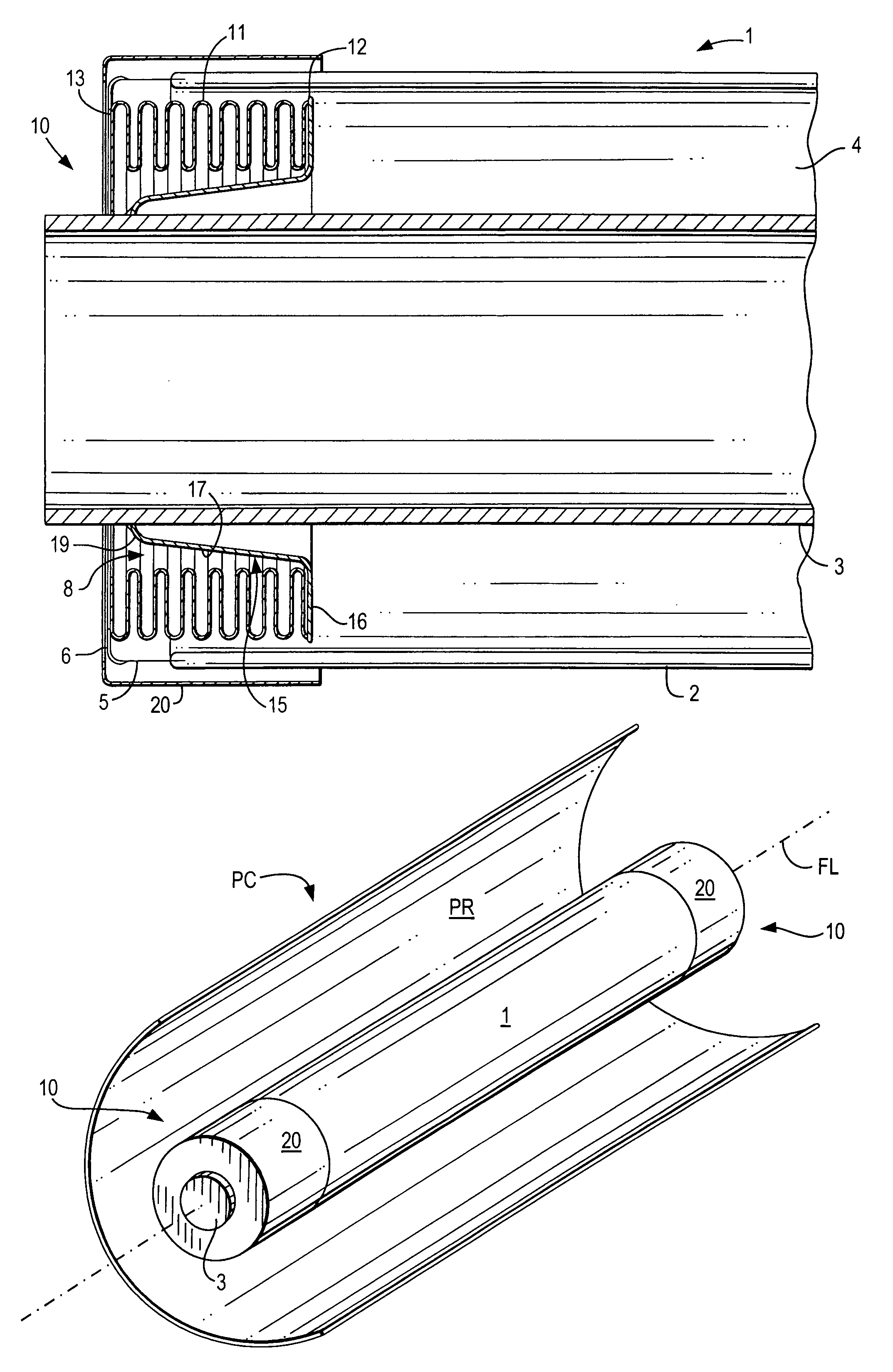
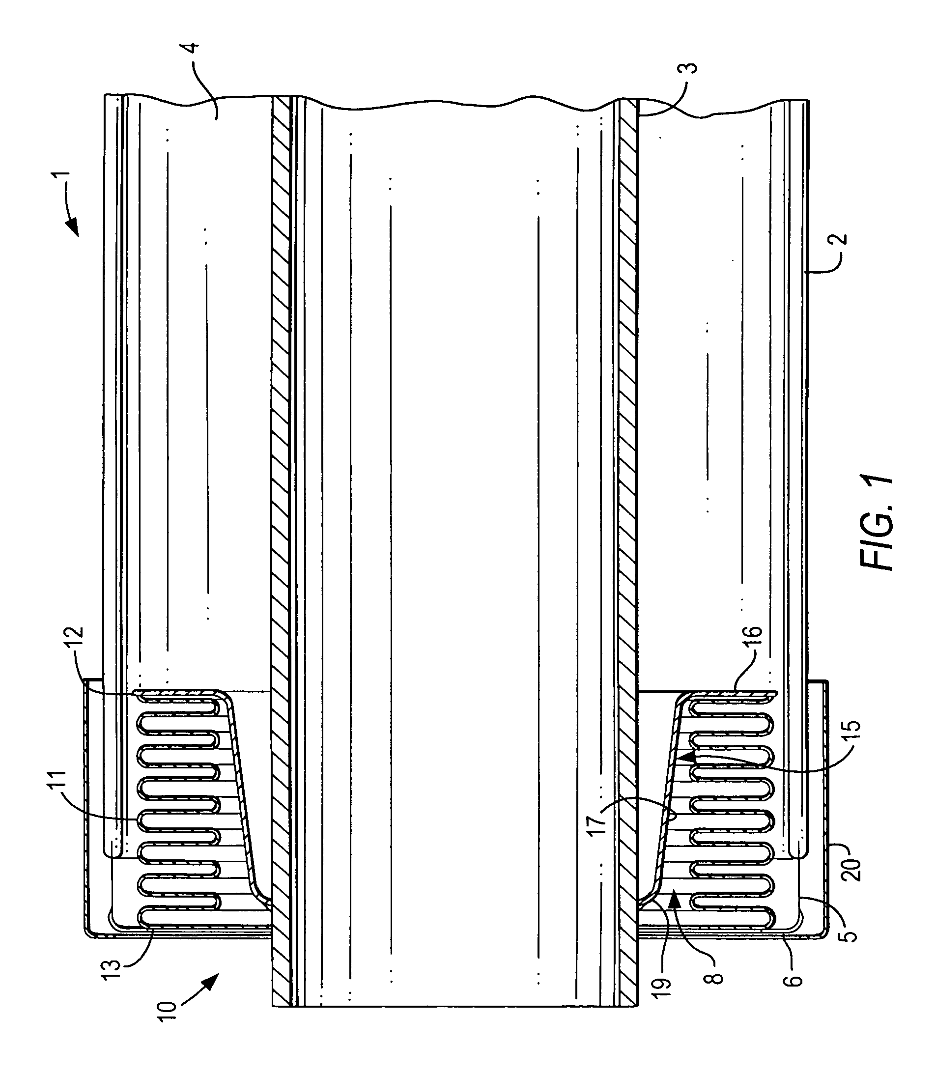
[0044]A longitudinal cross-sectional view through an end of the absorber pipe 1 is shown in FIG. 1. The absorber pipe 1 has a glass sleeve tube 2 and a central metal pipe 3 arranged concentrically in the glass sleeve tube 2. A radiation-selective coating for absorption of the solar radiation is provided on the outside of the metal pipe 3.

[0045]A glass-metal transitional element 5 is attached on the free front end of the sleeve tube 2. The glass-metal transitional element 5 has a radially inwardly pointing collar 6. The expansion compensation device 10 in the form of a folding bellows 11 is arranged in an annular space 4 between the sleeve tube 2 and the metal pipe 3. The outer end 13 of the folding bellows 11 is attached to the collar 6 of the glass-metal transitional element 5.

[0046]The folding bellows 11 extends adjacent the glass-metal transitional element 5 and into the annular space 4. The inner end 12 of the folding bellows 11, which is opposite from the outer end 13, is attac...


PUM


Abstract

The absorber pipe (1), especially for a parabolic collector for a solar heat collecting apparatus, is described. The absorber pipe (1) includes central metal pipe (3), a glass sleeve tube (2) surrounding the nine so that an annular space (4) is formed between them and an expansion compensating device connecting the central metal nine and a glass-metal transitional element (5) on a free end of the sleeve tube (2). The expansion compensation device (10) connects the metal pipe and sleeve tube, so that they can slide relative to each other, and includes folding bellows (11) for that purpose. Furthermore it also includes a connecting element (15), which has either a cylindrical or a conical section (17,18,18″) and which connects an interior end of the folding bellows with the metal pipe.

Description

BACKGROUND OF THE INVENTION[0001]1. Field of the Invention[0002]The present invention relates to an absorber pipe, especially for a parabolic collector in a solar heat collecting apparatus, which comprises a central metal pipe, a glass sleeve tube surrounding the central metal pipe to form an annular space between it and the central metal pipe, and a glass-metal transitional element arranged on a free end of the glass sleeve tube, wherein the central metal pipe and the glass-metal transitional element are connected with each other by means of at least one expansion compensating device so that they can move relative to each other in a longitudinal direction. The invention also relates to a parabolic collector using the absorber pipe and to the use of the absorber pipe.[0003]2. Description of the Related Art[0004]Parabolic collectors are described, for example, in “Journal of Solar Energy Engineering”, Vol. 124, p. 109 f, May 2002.[0005]The glass-metal connection is characterized by a...

Claims


Application Information

Patent Timeline
Patent Type & Authority Patents(United States)
IPC IPC(8): F24J2/24F16L27/12F16L27/00F24J2/46F24S10/40F24S10/70F24S20/20
CPCF24J2/055F24J2/07F24J2/4636Y02E10/44F24J2002/4681Y02E10/41F24S2025/6013F24S40/80F24S20/20F24S10/45Y02E10/40
Inventor KUCKELKORN, THOMASDOENITZ, FRITZ-DIETERBENZ, NIKOLAUS
Owner SCHOTT SOLAR CSP
Why Eureka
Try Eureka